Periodic electromagnetic separator with stirring device
A technology of stirring device and magnetic separator, which is applied in the field of mining equipment, can solve the problems such as difficult to clean out impurities and difficult to prepare high-quality fine powder, and achieve the effect of improving purity
- Summary
- Abstract
- Description
- Claims
- Application Information
AI Technical Summary
Problems solved by technology
Method used
Image
Examples
Embodiment 1
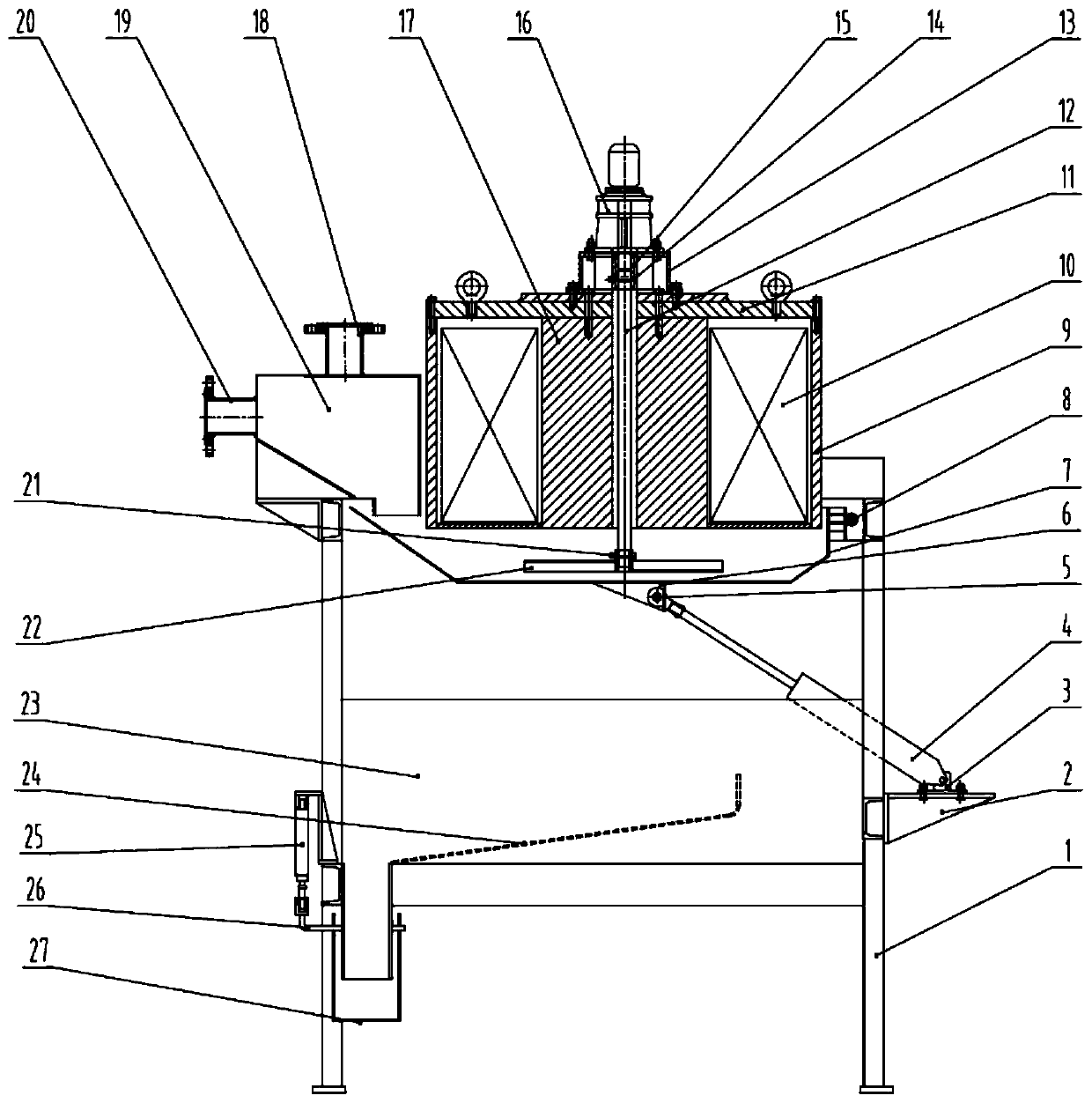
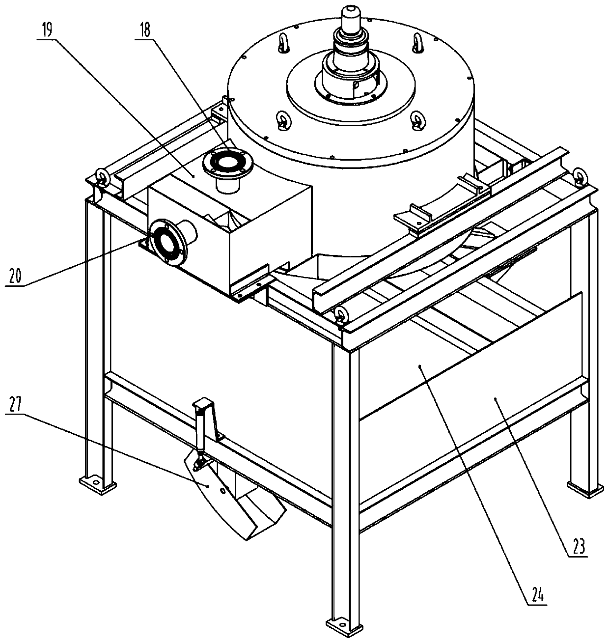
[0023] Such as figure 1 with 2 As shown, the periodic electromagnetic magnetic separator with a stirring device includes a frame 1, a stirring mechanism, an electromagnetic magnetic system, a feeding box 19, a tank body 7, a separation tank 27, a collection tank, and the top of the frame 1 is provided There is a feeding box 19 and an electromagnetic magnetic system. The upper part of the electromagnetic system is fixed with a stirring mechanism. The stirring rod 12 of the stirring mechanism passes through the hole in the middle of the iron core 17 and passes through the lower part. The lower part of the electromagnetic system is provided with a trough body 7. The body 7 is supported by the hinge 8 and the cylinder 4 fixed on the frame 1. The tail of the cylinder 4 is fixed on the support base 2 welded to the frame 1 by the cylinder fixing seat. The lower part of the tank body 7 is provided with a collection tank. A separation groove 27 is provided at the bottom of the, and the s...
Embodiment 2
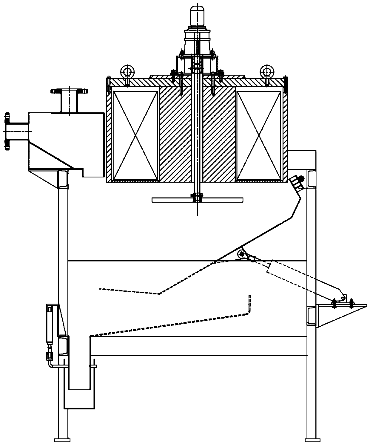
[0025] The periodic electromagnetic magnetic separator with a stirring device includes a frame 1, a stirring mechanism, an electromagnetic system, a feeding box 19, a tank body 7, a separation tank 27, and a collection tank. The top of the frame 1 is provided with a feeding tank. The box 19 and the electromagnetic magnetic system, the upper part of the electromagnetic magnetic system is fixed with a stirring mechanism, the stirring rod 12 of the stirring mechanism passes through the hole in the middle of the iron core 17 and penetrates the lower part. The lower part of the electromagnetic magnetic system is provided with a tank 7 through which the tank 7 passes The hinge 8 and the cylinder 4 fixed on the frame 1 are supported. The tail of the cylinder 4 is fixed on the support base 2 welded to the frame 1 through the cylinder fixing seat. The lower part of the tank body 7 is provided with a collection tank, and the bottom of the collection tank is provided There is a separation ...
Embodiment 3
[0028] The periodic electromagnetic magnetic separator with a stirring device includes a frame 1, a stirring mechanism, an electromagnetic system, a feeding box 19, a tank body 7, a separation tank 27, and a collection tank. The top of the frame 1 is provided with a feeding tank. The box 19 and the electromagnetic magnetic system, the upper part of the electromagnetic magnetic system is fixed with a stirring mechanism, the stirring rod 12 of the stirring mechanism passes through the hole in the middle of the iron core 17 and penetrates the lower part. The lower part of the electromagnetic magnetic system is provided with a tank 7 through which the tank 7 passes The hinge 8 and the cylinder 4 fixed on the frame 1 are supported. The tail of the cylinder 4 is fixed on the support base 2 welded to the frame 1 through the cylinder fixing seat. The lower part of the tank body 7 is provided with a collection tank, and the bottom of the collection tank is provided There is a separation ...
PUM
 Abstract
Description
Claims
Application Information
 - R&D
- Intellectual Property
- Life Sciences
- Materials
- Tech Scout
- Unparalleled Data Quality
- Higher Quality Content
- 60% Fewer Hallucinations
Browse by: Latest US Patents, China's latest patents, Technical Efficacy Thesaurus, Application Domain, Technology Topic, Popular Technical Reports.
© 2025 PatSnap. All rights reserved.Legal|Privacy policy|Modern Slavery Act Transparency Statement|Sitemap|About US| Contact US: help@patsnap.com


