
Test device for metal material creep under in-reactor radiation environment

A metal material and testing device technology, which is applied to measuring devices, analyzing materials, and testing the strength of materials by applying stable tension/pressure. Feasible and easy to achieve

Inactive Publication Date: 2019-07-09
NUCLEAR POWER INSTITUTE OF CHINA
View PDF10 Cites 2 Cited by
  • Summary
  • Abstract
  • Description
  • Claims
  • Application Information

AI Technical Summary

Problems solved by technology

There are no reports at home and abroad that can carry out material creep tests and obtain data under the irradiation environment in test reactors and commercial reactors

Method used


Image

  • Test device for metal material creep under in-reactor radiation environment
  • Test device for metal material creep under in-reactor radiation environment
  • Test device for metal material creep under in-reactor radiation environment

Examples


Embodiment 1

[0029] Experiments in the core fuel assembly guide tube of a pressurized water reactor nuclear power plant

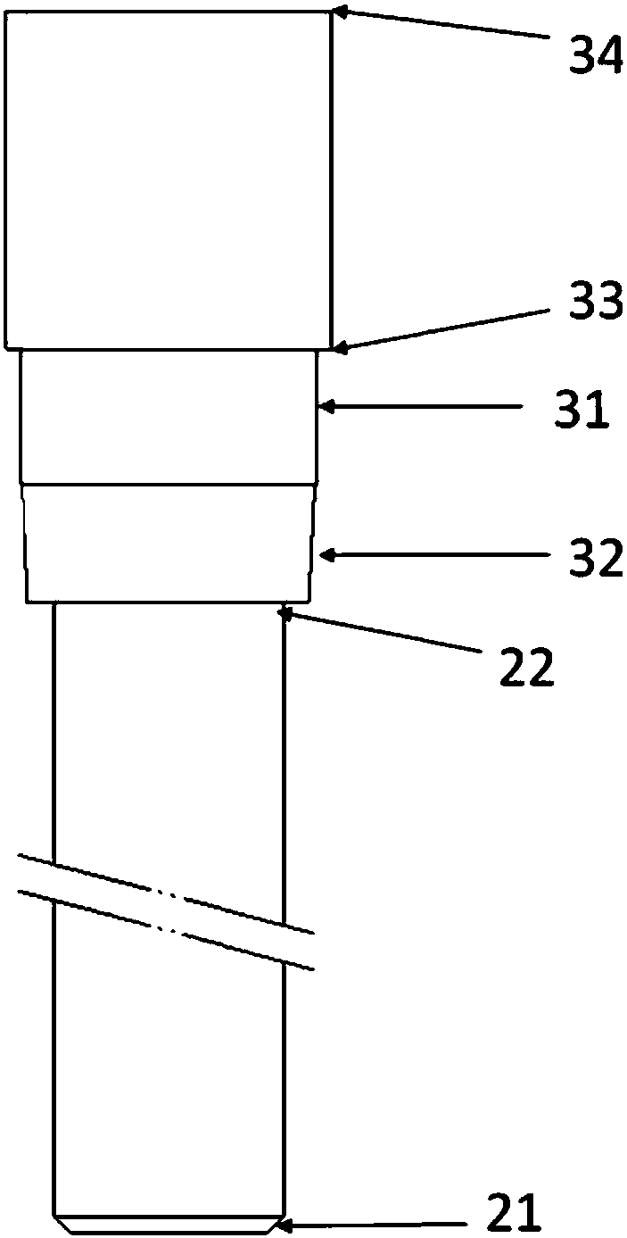
[0030] like Figure 5 As shown, a creep test device of the present invention is placed at the lower part of the choke rod 5, wherein the mandrel 2, the first end plug 3, and the choke rod 5 are formed into an integrated structure by machining. The upper structure of the choke rod 5 is the same as the choke rod of the conventional PWR choke plug assembly. After the integrated rod-shaped structure formed by the creep test device of the present invention and the choke rod 5, the conventional choke rod can be replaced.

[0031] The length and diameter of the choke rods 5 are kept the same as those of conventional choke rods, so that when used in the stack, the impact on the coolant flow path is expected to be small compared to the conventional choke rods, which can be compared with conventional choke rods. The flow stopper remains fairly effective.

[0032] The thin-wall...

Embodiment 2

[0036] Testing in the test reactor containment chamber

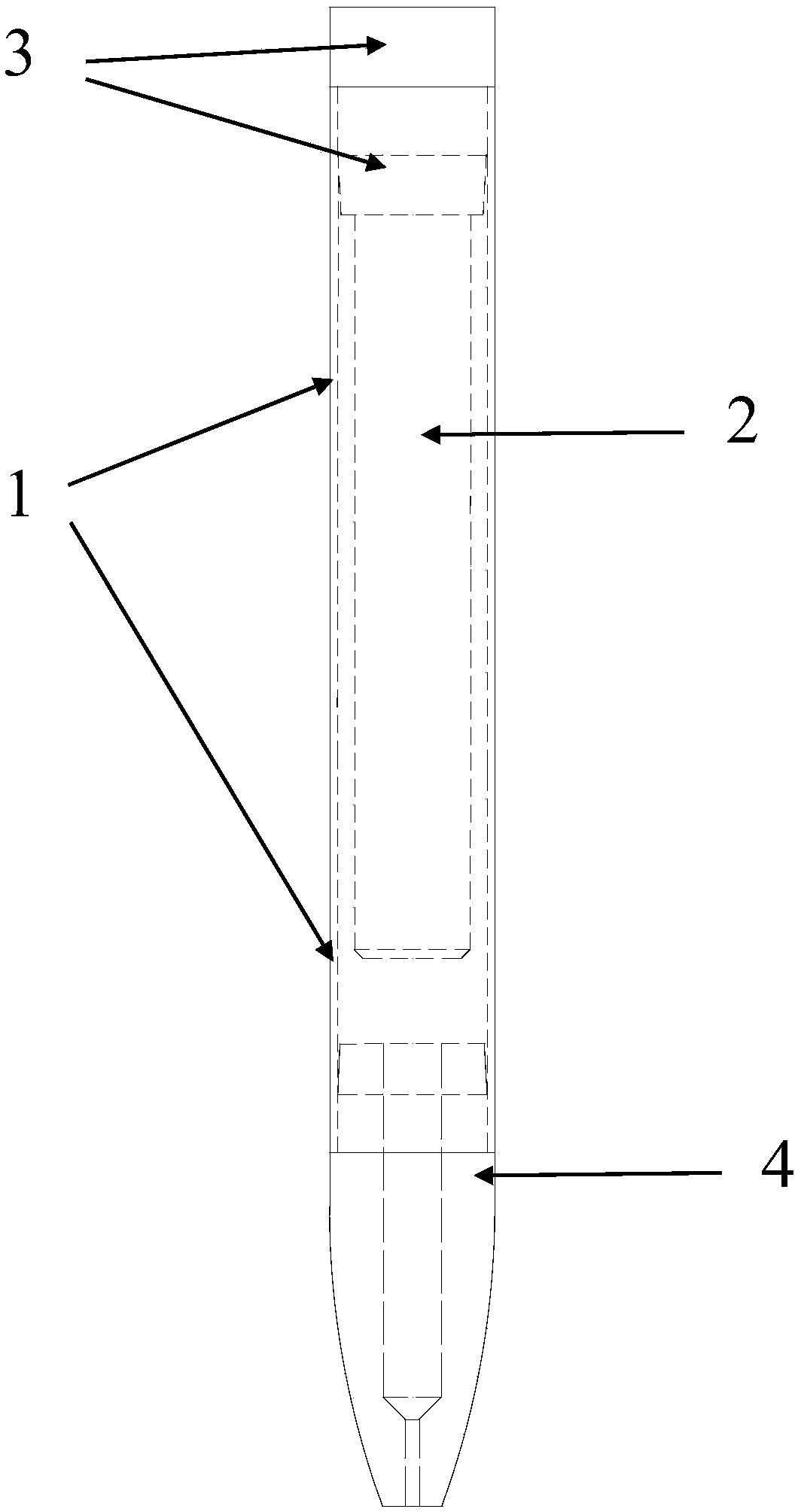
[0037] like Image 6 As shown, a metal material creep test device of the present invention is composed of a thin-walled round tube 1 , a mandrel 2 , a first end plug 3 , and a second end plug 4 . The second end plug 4 is slightly different from that in Embodiment 1, and the end portion is flat, so as to save the space of the irradiation test sealing chamber.

[0038] The thin-walled circular tube 1 has a wall thickness of 0.57 mm, a length of 100 mm, and an outer diameter of 9.5 mm. The mandrel is 5.36mm in diameter and 85mm in length. The gap between the mandrel and the inner wall of the round tube is 1.5mm. According to the needs of the test, the pre-filled helium gas pressure is between 0.1MPa and 7MPa.

[0039] The assembly process can refer to Example 1. During the test, with the help of the advanced deformation measurement tools of the test reactor, the real-time measurement of the creep deformation during the...


PUM

PropertyMeasurementUnit
thicknessaaaaaaaaaa
diameteraaaaaaaaaa
lengthaaaaaaaaaa

Abstract

The invention belongs to the technical field of nuclear reactor fuel, and particularly relates to a test device for metal material creep under the in-reactor radiation environment. The test device comprises a thin-walled circular pipe, a mandrel, a first end plug and a second end plug, the first end plug and the second end plug are fixedly connected with the upper end and the lower end of the thin-walled circular pipe correspondingly, the mandrel is arranged in the thin-walled circular pipe, one end of the mandrel is fixedly connected with the first end plug, gaps exist between the other end of the mandrel and the thin-walled circular pipe as well as between the other end of the mandrel and the second end plug, and the thin-walled circular pipe is pre-filled with pressure inert gas. The test device is simple in structure, convenient to realize and feasible in manufacturing, and the demands of cladding material creep test research and data acquisition under the irradiation environment in a test reactor and a commercial reactor can be met.

Description

technical field [0001] The invention belongs to the technical field of nuclear reactor fuel, and in particular relates to a test device for creep of metal materials in an irradiation environment in a reactor. Background technique [0002] The creep performance of fuel rod cladding material is one of the most important mechanical properties. Obtaining the creep performance of the fuel rod cladding material is very important for accurately predicting the irradiation behavior of fuel rod cladding in the reactor. In the research and development process of new cladding materials, how to obtain the in-stack creep test data of the new cladding materials, so as to obtain the creep properties of the cladding materials, has always been a difficult problem in the research and development of new cladding materials. [0003] The traditional material creep test is generally carried out in the external environment, and it is difficult to carry out the creep test in the irradiation environm...

Claims


Application Information

Patent Timeline
Patent Type & Authority Applications(China)
IPC IPC(8): G01N3/12
CPCG01N3/12G01N2203/0019G01N2203/0071G01N2203/0236
Inventor 高士鑫王坤张坤雷涛陈平焦拥军吕亮亮吴磊刘振海邢硕
Owner NUCLEAR POWER INSTITUTE OF CHINA
Learn More