
Hydrogenation reactor with flush plate on the top

A hydrogenation reactor and reactor technology, applied in the direction of chemical instruments and methods, chemical/physical processes, etc., can solve the problems of reducing the service life of the catalyst, damaging the performance of the catalyst, and varying the degree of reaction, so as to improve the distribution of materials, optimize the Effect of material distribution, uniform inlet conditions

Active Publication Date: 2021-08-31
CHINA PETROLEUM & CHEM CORP +1
View PDF9 Cites 0 Cited by
  • Summary
  • Abstract
  • Description
  • Claims
  • Application Information

AI Technical Summary

Problems solved by technology

Since the hydrogenation process is an exothermic reaction, the feedstock oil is unevenly distributed on the radial section of the catalyst bed, which will lead to different reaction degrees and radial temperature differences, and even local overheating, which will damage the performance of the catalyst and greatly reduce the catalyst performance. life cycle

Method used


Image

  • Hydrogenation reactor with flush plate on the top
  • Hydrogenation reactor with flush plate on the top
  • Hydrogenation reactor with flush plate on the top

Examples


Embodiment 1

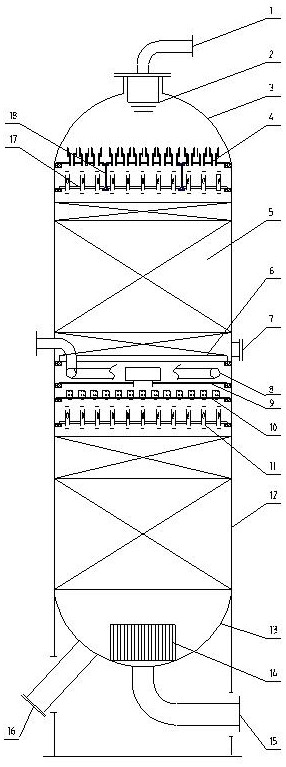
[0073] Compared with Example 1, in the upper head of the hydrogenation reactor, the bubble-cap type gas-liquid distributor is replaced by the folded-type spray plate of the present invention, and the folded-type injection plate of the present invention is used to replace the gas-liquid distributor. Flat tower sieve plate hole structure. The main parameters of the sleeve-type shock-reducing flow distribution plate are: the height of the shock-reducing barrel is preferably 300mm; the diameter of the shock-reducing barrel is preferably 150mm; 10%. The horizontal gap between the impact reduction cylinder and the chimney distributor is preferably 30mm; the cross-sectional area of ​​the impact reduction cylinder is 5 times the cross-sectional area of ​​the chimney distributor; the bottom edge of the impact reduction cylinder overlaps with the chimney distributor; the overlapping position is the height of the chimney distributor 20% of the chimney distributor; the height of the chim...

Embodiment 2

[0077] Compared with Example 1, the folded-edge type shock-reducing equalizer plate of the present invention is arranged above the bubble-cap type gas-liquid distributor in the upper head of the hydrogenation reactor, and the flat plate is replaced by the folded-edge spray plate of the present invention. Tower sieve tray hole structure. The main parameters of the sleeve-type shock-reducing flow distribution plate are: the height of the shock-reducing barrel is preferably 300mm; the diameter of the shock-reducing barrel is preferably 150mm; 10%. The horizontal gap between the impact reduction cylinder and the chimney distributor is preferably 30mm; the cross-sectional area of ​​the impact reduction cylinder is 5 times the cross-sectional area of ​​the chimney distributor; the bottom edge of the impact reduction cylinder overlaps with the chimney distributor; the overlapping position is the height of the chimney distributor 20% of the chimney distributor; the height of the chim...


PUM


Abstract

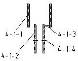
The invention discloses a hydrogenation reactor with an impact-relief plate arranged on the top. The hydrogenation reactor of the present invention includes a material inlet pipe, an inlet diffuser, an upper head of the reactor, a sleeve-type flush reducing and equalizing plate, a catalyst bed, a catalyst support grid, a reactor cylinder, and a lower head of the reactor. , outlet collector, material outlet pipe and unloading pipe. The sleeve-type anti-shock equalizer includes a tray and a number of chimney distributors vertically arranged on the tray; the chimney distributor includes a downcomer and a downcomer arranged at the upper end of the downcomer ; The flanged spray tray includes a tray and several chimney distributors vertically arranged on the tray; the chimney distributor includes a downcomer and a wing plate arranged on the top of the downcomer. The hydrogenation reactor of the present invention is suitable for all hydrogenation reaction processes, especially hydrofinishing or hydrocracking processes with relatively large reactor scales.

Description

technical field [0001] The invention relates to a hydrogenation reactor, which belongs to the field of chemical equipment. The hydrogenation reactor of the present invention is suitable for all hydrogenation reaction processes, especially hydrofinishing or hydrocracking processes with relatively large reactor scales. Background technique [0002] In recent years, with the rapid economic development and the enhancement of environmental protection awareness, the quality and environmental protection requirements of petrochemical products are getting higher and higher. As one of the technical means to produce clean fuels, hydrogenation technology plays an increasingly important role in the oil refining industry. In the hydrogenation unit, like the hydrogenation catalyst technology and the hydrogenation process technology, the hydrogenation reactor technology is an important part of the reactor system, and the three constitute the three factors of the reactor performance. In th...

Claims


Application Information

Patent Timeline
Patent Type & Authority Patents(China)
IPC IPC(8): B01J8/04
CPCB01J8/0446
Inventor 彭德强王璐瑶刘杰
Owner CHINA PETROLEUM & CHEM CORP
Learn More