Low-noise permanent magnet synchronous motor rotor initial position detection method

A permanent magnet synchronous motor, rotor initial position technology, applied in the direction of electronic commutator, motor control, control generator, etc., can solve the problems of large vibration and noise, limit, etc., to eliminate vibration and noise, reduce high-frequency noise , The signal processing method is simple and easy to implement

Active Publication Date: 2019-07-05
HARBIN INST OF TECH
View PDF6 Cites 10 Cited by
  • Summary
  • Abstract
  • Description
  • Claims
  • Application Information

AI Technical Summary

Problems solved by technology

[0006] The purpose of the present invention is to solve the problem that the traditional initial position detection method produces relatively large vibration and noise when detecting the position and polarity of the magnetic pole,...

Method used


Image

  • Low-noise permanent magnet synchronous motor rotor initial position detection method
  • Low-noise permanent magnet synchronous motor rotor initial position detection method
  • Low-noise permanent magnet synchronous motor rotor initial position detection method

Examples


Embodiment Construction

[0062] The following will clearly and completely describe the technical solutions in the embodiments of the present invention with reference to the accompanying drawings in the embodiments of the present invention. Obviously, the described embodiments are only some, not all, embodiments of the present invention. Based on the embodiments of the present invention, all other embodiments obtained by persons of ordinary skill in the art without making creative efforts belong to the protection scope of the present invention.

[0063] It should be noted that, in the case of no conflict, the embodiments of the present invention and the features in the embodiments can be combined with each other.

[0064] The present invention will be further described below in conjunction with the accompanying drawings and specific embodiments, but not as a limitation of the present invention.

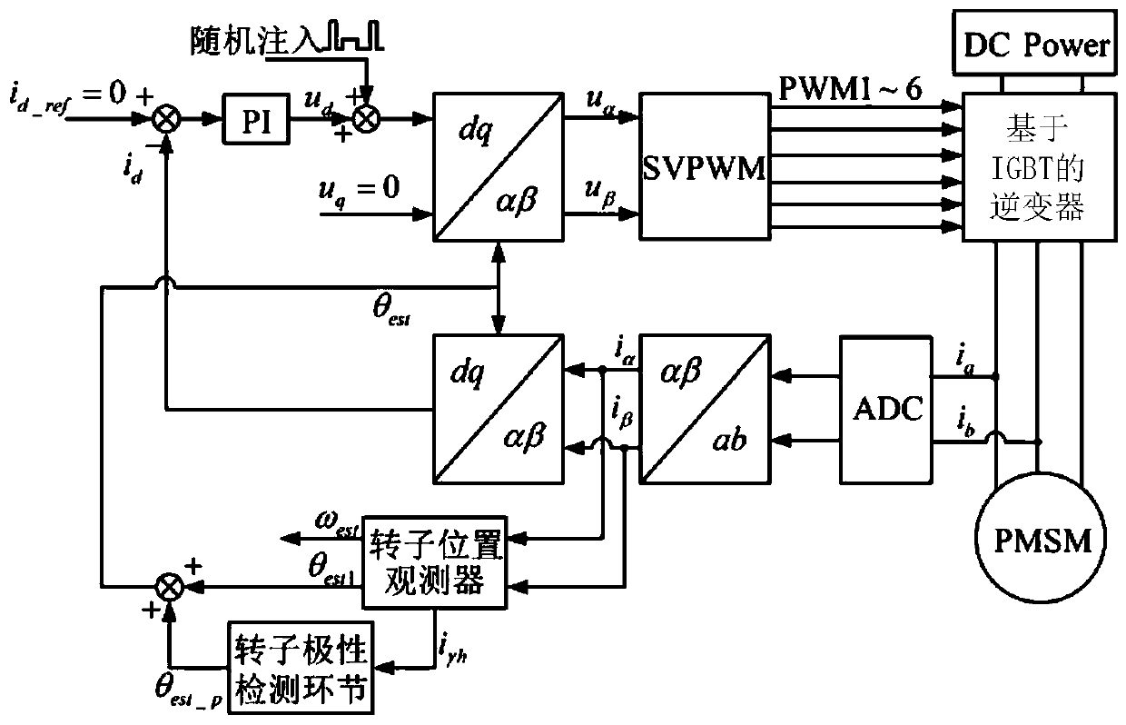
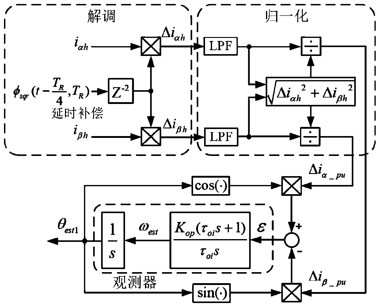
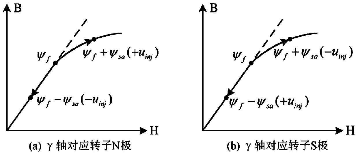
[0065] see figure 1 Describe this embodiment, a low-noise permanent magnet synchronous motor rotor initial...


PUM


Abstract

The invention discloses a low-noise permanent magnet synchronous motor rotor initial position detection method, and relates to the field of motor control. The problem that the traditional initial position detection method generates relatively big vibration and loud noise when the position and the polarity of a magnetic pole is detected, so that the application thereof is limited in certain occasions with higher requirements on noise is solved. The method comprises the following steps: Step 1, identifying an estimated value theta est1 of the initial position of the magnetic pole by adopting a voltage injection method based on random high-frequency square wave aiming at a high-frequency mathematical model of a built-in permanent magnet synchronous motor; Step 2, observing the sign of the accumulated value of the high-frequency response current peak value of a gamma axis in the high-frequency mathematical model of the built-in permanent magnet synchronous motor based on the stator core saturation nonlinearity principle, and identifying the polarity information of the magnetic pole of a rotor; and Step 3, correcting and compensating the estimated value theta est1 of the initial position of the magnetic pole according to the polarity information of the magnetic pole of the rotor to obtain the estimated value theta est of the initial position of the rotor. The low-noise permanent magnet synchronous motor rotor initial position detection method is mainly used for detecting the initial position of the permanent magnet synchronous motor rotor.

Description

technical field [0001] The invention relates to the field of motor control. Background technique [0002] With the development of mechanization and electrification in the world, the motor has always been a very important link in the process of electromechanical energy conversion. In recent years, permanent magnet synchronous motors have become an ideal choice for frequency conversion and speed regulation electric drive systems due to their simple structure, small size, high power density, high efficiency, and good speed regulation performance. They have outstanding performance in the field of small and medium power applications. . Since permanent magnets are installed on the rotor, no additional current is required to excite the PMSM rotor. According to the structure of the permanent magnet synchronous motor rotor, it can be divided into two types: surface mount type and built-in type. [0003] At present, in the application of high-performance permanent magnet synchronou...

Claims


Application Information

Patent Timeline
IPC IPC(8): H02P6/18H02P6/34H02P21/32
CPCH02P6/183H02P6/34H02P21/32H02P2203/03H02P2203/11
Inventor 张国强毕广东王高林赵楠楠王奇维李成睿徐殿国
Owner HARBIN INST OF TECH
Why Eureka
Try Eureka