


Quick Research
Generate reliable direction feasibility study reports for your R&D in just a few steps.

Technical Q&A
Discover and master advanced knowledge NOW. Basics, ideas, possibilities, all at once.

Find Solutions
As an expert in R&D theories, this can generate solutions to your technical problems instantly.

Evaluate Feasibility
Analyze your overall solution with one click, know your potential R&D risks in advance.

Monitor Landscape
Get weekly tech updates, stay abreast of the latest tech innovations and key insights.
Simple soft start circuit
A soft-start circuit and drive circuit technology, applied in electrical components, output power conversion devices, etc., to achieve the effects of small voltage drop, high power efficiency, and low temperature
- Summary
- Abstract
- Description
- Claims
- Application Information
AI Technical Summary
Problems solved by technology
Method used
Image

Examples
Embodiment 1
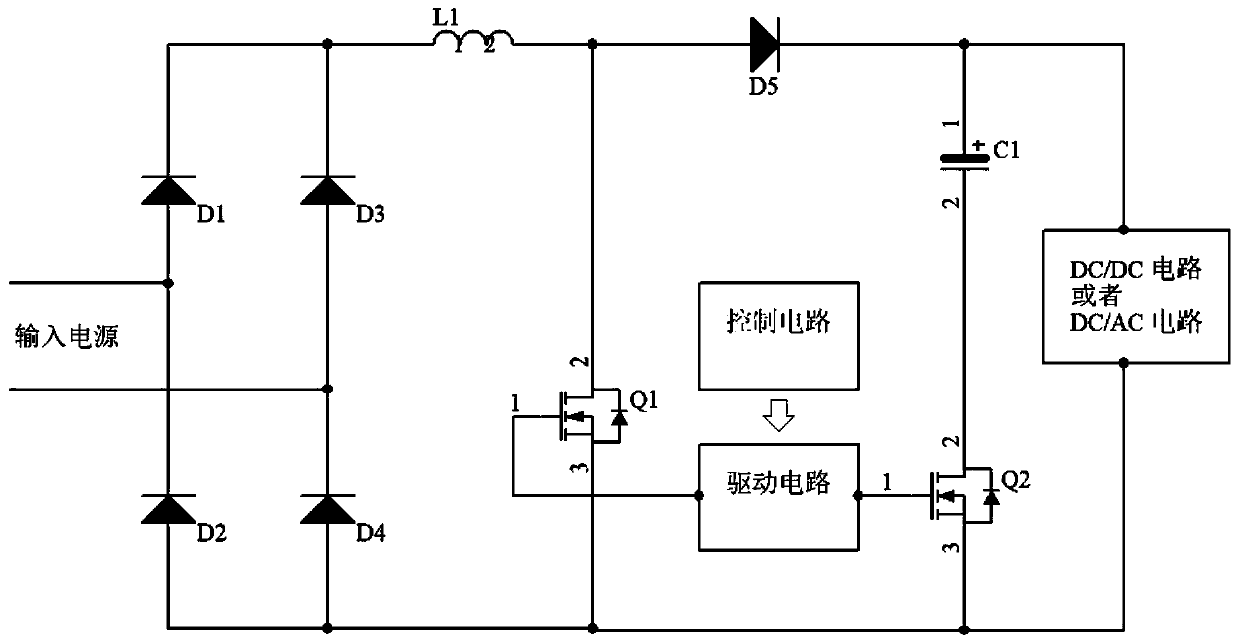
[0047] like figure 2 As shown, the soft start circuit includes a rectifier circuit, a DC / DC or DC / AC conversion circuit connected to the load, an inductor L1, a capacitor C1, and two switch tubes Q1 and Q2; the inductor L1 is connected to one end of the rectifier circuit, and the first The two ends of the switch tube Q1 are connected in parallel to the rectifier circuit and the two ends of the inductance L1, and the capacitor C1 is connected in parallel to the two ends of the conversion circuit;
[0048] A diode D5 is set between the inductance L1 and the capacitor C1; a second switch tube Q2 is set between the connection midpoint of the rectifier circuit and the conversion circuit and the capacitor C1, and the gates of the first switch tube Q1 and the second switch tube Q2 are simultaneously Connected to the drive circuit, the drive circuit is connected to the control circuit.
[0049] In this example, the current flowing through the second switching tube Q2 is the same as ...
Embodiment 2
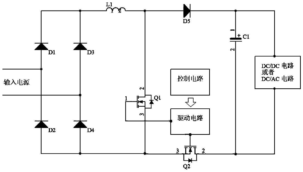
[0051] like image 3 As shown, the soft start circuit includes a rectifier circuit, a DC / DC or DC / AC conversion circuit connected to the load, an inductor L1, a capacitor C1, and two switch tubes Q1 and Q2; the inductor L1 is connected to one end of the rectifier circuit, and the first The two ends of the switch tube Q1 are connected in parallel to the rectifier circuit and the two ends of the inductance L1, and the capacitor C1 is connected in parallel to the two ends of the conversion circuit;
[0052] A diode D5 is provided between the inductor L1 and the capacitor C1; the two ends of the second switching tube Q2 are respectively connected to the rectifier circuit and the conversion circuit and are on different sides from the inductor L1, and the gates of the first switching tube Q1 and the second switching tube Q2 are connected simultaneously. To the drive circuit, the drive circuit is connected to the control circuit;
[0053] In this embodiment, the current flowing thro...
Embodiment 3
[0055] like Figure 4 As shown, the soft start circuit includes a rectifier circuit, a DC / DC or DC / AC conversion circuit connected to the load, an inductor L1, a capacitor C1, and two switch tubes Q1 and Q2; the inductor L1 is connected to one end of the rectifier circuit, and the first The two ends of the switch tube Q1 are connected in parallel to the rectifier circuit and the two ends of the inductance L1, and the capacitor C1 is connected in parallel to the two ends of the conversion circuit;
[0056] A second switching tube Q2 is provided between the inductor L1 and the capacitor C1; the gates of the first switching tube Q1 and the second switching tube Q2 are simultaneously connected to the driving circuit, and the driving circuit is connected to the control circuit;
[0057] In this embodiment, the flow through the second switch tube Q2 is the same as in embodiment 2, but compared with embodiments 1 and 2, there is one less diode, that is, the second switch tube Q2 is u...
PUM
 Abstract
Description
Claims
Application Information
 - R&D Engineer
- R&D Manager
- IP Professional
- Industry Leading Data Capabilities
- Powerful AI technology
- Patent DNA Extraction
Browse by: Latest US Patents, China's latest patents, Technical Efficacy Thesaurus, Application Domain, Technology Topic, Popular Technical Reports.
© 2024 PatSnap. All rights reserved.Legal|Privacy policy|Modern Slavery Act Transparency Statement|Sitemap|About US| Contact US: help@patsnap.com