Clock frequency test circuit and measurement calculation method
A technology of clock frequency and test circuit, which is applied in the field of clock frequency test circuit, can solve the problems of large error, large frequency error of measurement and calculation, and long time of measurement and calculation
- Summary
- Abstract
- Description
- Claims
- Application Information
AI Technical Summary
Problems solved by technology
Method used
Image
Examples
Embodiment Construction
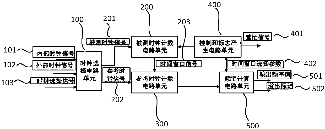
[0036] A clock frequency test circuit such as figure 1 shown, including:
[0037] Clock selection circuit unit 100, used for input selection of internal and external clock signals;
[0038] The measured clock counting circuit unit 200 receives the measured clock signal 201 transmitted by the clock selection circuit unit 100, and is used to generate a suitable time window signal 203;
[0039] The reference clock counting circuit unit 300 receives the reference clock signal 202 transmitted by the clock selection circuit unit 100 and at the same time receives the time window signal 203 generated by the measured clock counting circuit unit 200 for counting;
[0040] The control and sign generation circuit unit 400 is used to start the measured clock counting circuit unit 200 and the reference clock counting circuit unit 300 to realize the reset of the corresponding counting circuit unit;
[0041] The frequency calculation circuit unit 500 receives the time window selection param...
PUM
 Abstract
Description
Claims
Application Information
 - R&D
- Intellectual Property
- Life Sciences
- Materials
- Tech Scout
- Unparalleled Data Quality
- Higher Quality Content
- 60% Fewer Hallucinations
Browse by: Latest US Patents, China's latest patents, Technical Efficacy Thesaurus, Application Domain, Technology Topic, Popular Technical Reports.
© 2025 PatSnap. All rights reserved.Legal|Privacy policy|Modern Slavery Act Transparency Statement|Sitemap|About US| Contact US: help@patsnap.com


