
lidar

A laser radar and laser technology, applied in the field of laser detection, can solve the problems of optical system redundancy, high cost, poor working stability, etc.

Active Publication Date: 2020-04-28
SUTENG INNOVATION TECH CO LTD
View PDF6 Cites 0 Cited by
  • Summary
  • Abstract
  • Description
  • Claims
  • Application Information

AI Technical Summary

Problems solved by technology

[0003] Based on this, it is necessary to provide a laser radar for the problems that the entire optical system is relatively redundant when the traditional laser radar adopts an off-axis transceiver structure, which will bring higher cost and poor work stability.

Method used


Image

  • lidar
  • lidar
  • lidar

Examples


Embodiment Construction

[0024] In order to make the purpose, technical solution and advantages of the present application clearer, the present application will be further described in detail below in conjunction with the accompanying drawings and embodiments. It should be understood that the specific embodiments described here are only used to explain the present application, and are not intended to limit the present application.

[0025] In the description of the present application, it should be understood that the terms "central", "lateral", "upper", "lower", "left", "right", "vertical", "horizontal", "top", " The orientation or positional relationship indicated by "bottom", "inner" and "outer" are based on the orientation or positional relationship shown in the drawings, which are only for the convenience of describing the application and simplifying the description, rather than indicating or implying the referred device or positional relationship. Elements must have certain orientations, be cons...


PUM


Abstract

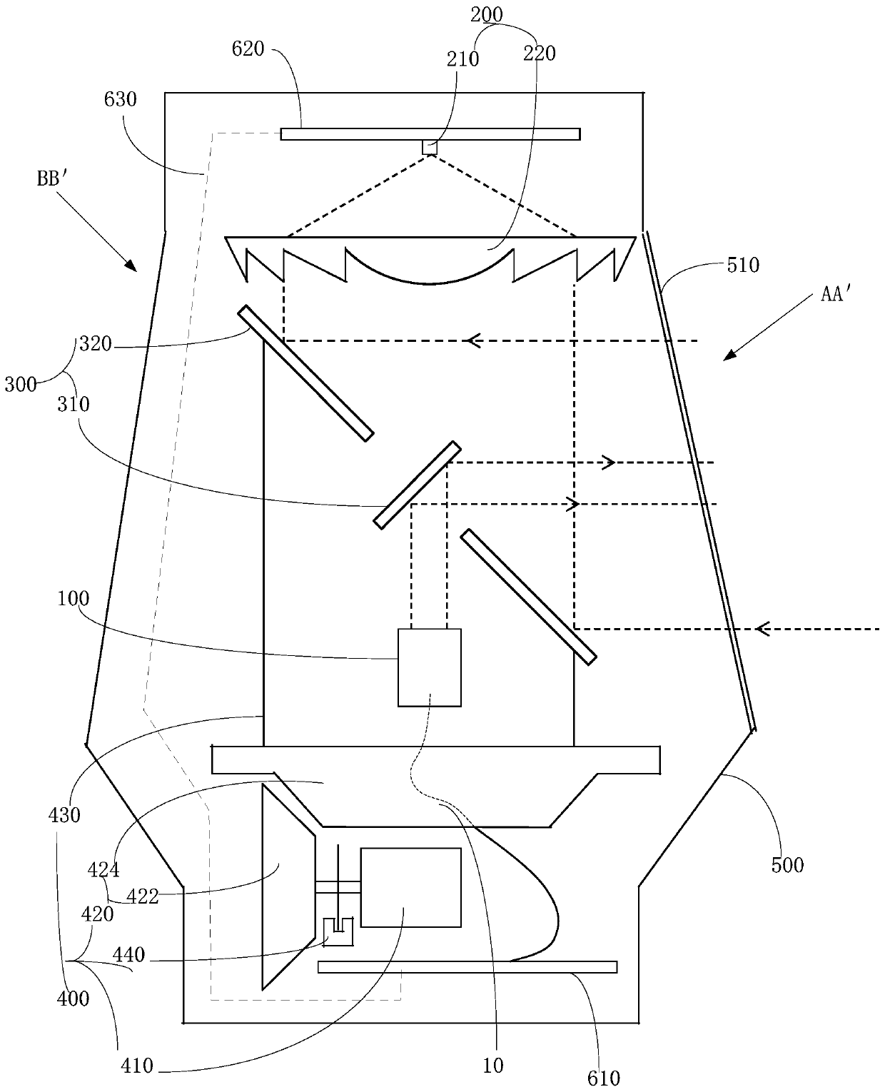
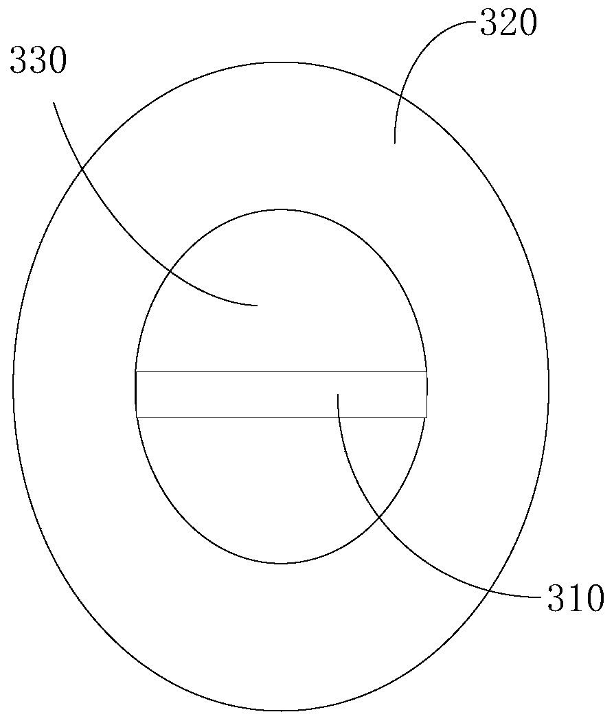
A laser radar is disclosed. The laser radar comprises a laser emission device, a laser receiving device, a reflection component and a rotation driving device, wherein the laser emission device is usedfor generating an emission laser; the laser receiving device is oppositely arranged with the laser emission device; the reflection component is arranged between the laser emission device and the laser receiving device; the reflection component includes a first reflection mirror and a second reflection mirror which are mutually and fixedly connected; the second reflection mirror surrounds the first reflection mirror and there is a gap between the second reflection mirror and a mirror surface of the first reflection mirror; the mirror surface of the first reflection mirror faces towards the laser emission device so as to project the emission laser to a detected target; the mirror surface of the second reflection mirror faces towards the laser receiving device so as to project a reflected laser reflected by the detected target to the laser receiving device; and the rotation driving device is connected to the reflection component and is used for driving the reflection component to rotateso that the emission laser carries out scanning in different directions. Through the above structure of the laser radar, low cost and a stable working state can be brought.

Description

technical field [0001] The invention relates to the technical field of laser detection, in particular to a laser radar. Background technique [0002] Lidar is a system that emits laser beams to detect characteristic quantities such as the position and speed of targets, and is widely used in the field of laser detection. LiDAR is an energy transceiving system. In optical design, there are two modes of coaxial transceiving and off-axis transceiving. In terms of mechanical structure, there are two modes of same-side transceiving and transceiving separation. Among them, the off-axis transceiver structure can avoid the interference of stray light, but the entire optical system is relatively redundant, which will bring higher cost and poor working stability. Contents of the invention [0003] Based on this, it is necessary to provide a laser radar for the problems that the entire optical system is relatively redundant when the traditional laser radar adopts an off-axis transcei...

Claims


Application Information

Patent Timeline
Patent Type & Authority Patents(China)
IPC IPC(8): G01S7/481
CPCG01S7/481G01S7/4812G01S7/4813G01S7/4817
Inventor 尹向辉
Owner SUTENG INNOVATION TECH CO LTD
Learn More