
High energy consumption damping wall

A damping wall, high energy consumption technology, applied in the field of high-rise structure vibration reduction, can solve problems such as limited, achieve the effect of reversible process and fast response

Pending Publication Date: 2019-07-05
SHENYANG JIANZHU UNIVERSITY +1
View PDF0 Cites 0 Cited by
  • Summary
  • Abstract
  • Description
  • Claims
  • Application Information

AI Technical Summary

Problems solved by technology

[0006] Aiming at the problem that the traditional viscous damping wall has constant and limited damping force on the upper part of high-rise buildings when wind or earthquake occurs, the present invention provides a high-energy-consuming damping wall, which uses a scissor mechanism to amplify the dynamic force between adjacent floors Response, make it stimulate the shear thickening mechanism of STF, generate high damping force instantly, thereby consume external energy, because STF has the characteristics of instantaneous response, high energy consumption, process reversibility and no external energy input, etc., therefore, the present invention has Intelligent, fast response, high energy consumption, etc.

Method used


Image

  • High energy consumption damping wall
  • High energy consumption damping wall
  • High energy consumption damping wall

Examples


Embodiment 1

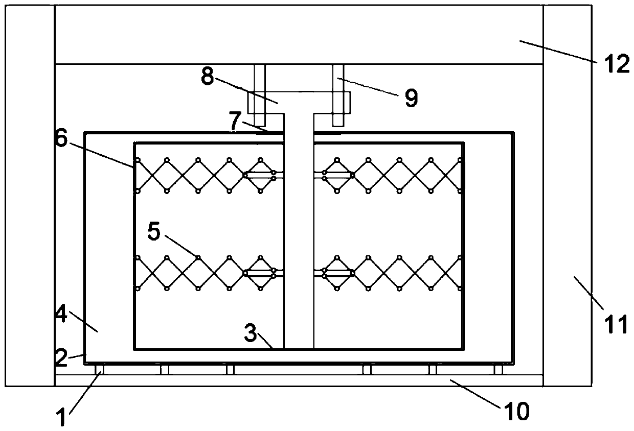
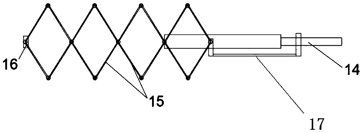
[0032] Embodiment 1: as figure 1 , figure 2 As shown, the present invention includes a high energy consumption damping wall, including a damping plate outer frame, a damping plate and a T-shaped structure arranged in the wall;

[0033] The outer frame of the damping plate 2, the lower part is fixed on the lower floor 10 through the connector I1;

[0034] A plurality of damping plates 6 are arranged in the outer frame of the damping plate 2. In this example, three damping plates 6 are arranged in parallel, and a working chamber 4 is formed in the outer frame of the damping plate 2 and between the adjacent damping plates 6. The working chamber 4 The inside is filled with a shear thickening liquid; several scissor mechanisms 5 are arranged inside each damping plate;

[0035] T-shaped structure 8, the upper horizontal part is fixed on the lower main beam 12 of the upper floor through the connector II9, the lower vertical part penetrates the damping plate frame 2 and the damping...

Embodiment 2

[0042] Embodiment 2: The difference between this example and Embodiment 1 is: the wall structure in this example: 240mm×6000mm×3600mm, 2 damping plates are arranged in it, the distance between the inner adjacent damping plates 6 of the outer frame 2 and The distance between the edge damping plate and the outer frame of the damping plate is 2.0 mm; the scissor mechanism 5 arranged in the damping plate 6 is two symmetrical rows, and the relative speed of the high-rise building layer is multiplied by the scissor mechanism 5 (this example uses magnified by 5 times or more), at this time, the STF inside the working chamber 4 will be squeezed at a relatively high rate by the damping plate 6 and flow into the gap of the damping plate 6, and the STF will rapidly undergo shear thickening during this process Effect, generate damping force, so as to realize the vibration reduction and energy consumption of high-rise building structures, and achieve the vibration reduction effect.

Embodiment 3

[0043] Embodiment 3: The difference between this example and Embodiment 1 is: the wall structure in this example: 300mm × 6300mm × 3900mm in which 3 damping plates are arranged, the distance between the inner adjacent damping plates 6 of the outer frame 2 and the edge The distance between the damping plate and the outer frame of the damping plate is 1.0mm; the scissor mechanism 5 arranged in the damping plate 6 is two symmetrical rows, and the relative velocity of the high-rise building layer is multiplied by the scissor mechanism 5. In this example, the magnification 8 times, realize the vibration reduction and energy consumption of high-rise building structures, and achieve the vibration reduction effect.


PUM


Abstract

The invention discloses a high energy consumption damping wall, and belongs to the technical field of high-rise structure vibration reduction. The high energy consumption damping wall comprises damping plate outer frames, damping plates, and a T-shaped structure; the damping plate outer frames are fixed to a lower floor slab; the multiple damping plates are arranged in the damping plate outer frames, and working chambers formed in the positions, between the adjacent damping plates, in the damping plate outer frames are filled with shear thickening fluids (STF) correspondingly; the horizontal part of the T-shaped structure is fixedly connected with an adjacent last floor structure, the lower vertical part of the T-shaped structure penetrates into the damping plate outer frames and the damping plates, the end of the T-shaped structure is connected to the bottom edges of the damping plates, and the two sides of the T-shaped structure are connected with the damping plates and the damping plate outer frames respectively; a plurality of shear mechanisms are arranged in the damping plates, one ends of the shear mechanisms are fixedly connected with the T-shaped structure, the other ends of the shear mechanisms are directionally hinged to the damping steel plates, and the shear mechanisms are arranged parallel to the plate surfaces of the damping plates; and when a high-rise structureproduces shaking, power of adjacent floors is amplified by the shear mechanisms, the damping plates squeeze the STFs at the high rate, the shear thickening properties of the STFs are excited, high damping force is produced instantaneously, and external input energy is consumed.

Description

technical field [0001] The invention belongs to the technical field of vibration reduction of high-rise structures, in particular to a high-energy-consuming damping wall. Background technique [0002] Since the 1980s, with the continuous deepening of reform and opening up, high-rise buildings have also developed. High-rise residential buildings provide a guarantee for the rapid increase of urban population. Therefore, in the central areas of large and medium-sized cities, it is imperative to build high-rise buildings. [0003] In the United States, the development of high-rise buildings has matured, while the golden period for the development of high-rise buildings in my country was the 1980s and 1990s. Both the quality and quantity of high-rise buildings have developed rapidly. For example, the Shanghai Jinmao Tower in 1998 had 88 floors and a height of 420 meters; the CITIC Plaza built in Guangzhou in 1996 had 80 floors and a height of 391 meters. Since then, the enthusi...

Claims


Application Information

Patent Timeline
IPC IPC(8): E04B2/56E04B1/98E04H6/02
CPCE04B2/56E04H9/021E04H9/023
Inventor 魏明海孙丽刘海涛齐倍莹
Owner SHENYANG JIANZHU UNIVERSITY
Learn More