Hand relieving mechanism of parking braking cylinder

A first-hand technology for parking brakes, applied to the operating mechanism of railway vehicle brakes, railway braking systems, railway car body parts, etc. Small workload, easy disassembly and simple structure

Pending Publication Date: 2019-07-05
四川江山轨道交通装备制造有限公司
View PDF0 Cites 1 Cited by
  • Summary
  • Abstract
  • Description
  • Claims
  • Application Information

AI Technical Summary

Problems solved by technology

[0003] The existing hand relief mechanism realizes the two-way toggle of the pawl by setting the torsion spring and the cable. However, the torsion spring will fail due to excessive use time during use, and it is troublesome to disassemble during maintenance.

Method used


Image

  • Hand relieving mechanism of parking braking cylinder
  • Hand relieving mechanism of parking braking cylinder
  • Hand relieving mechanism of parking braking cylinder

Examples


Embodiment 1

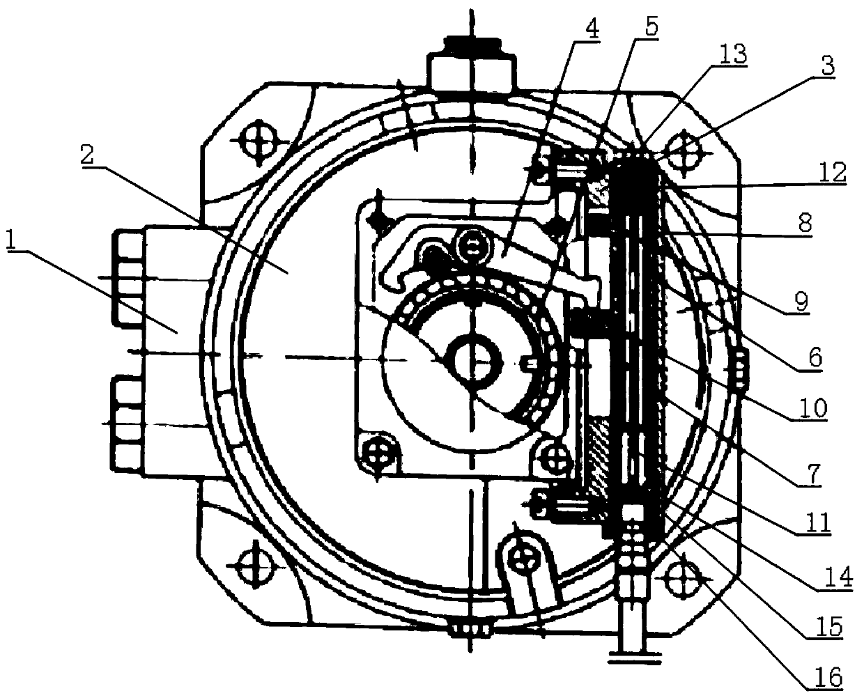
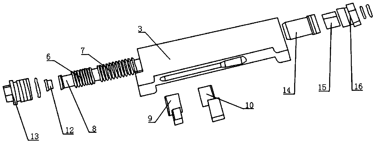
[0030] Such as figure 1 with figure 2 As shown, a hand relief mechanism for a parking brake cylinder is provided on the cylinder head 2 of the parking brake cylinder 1, and the hand relief mechanism includes a hand relief body 3, a pawl 4, and a ratchet sleeve 5 , the first hand relief spring 6, the second hand relief spring 7, the hand relief sliding sleeve 8, the first pawl toggle sleeve 9 and the second pawl toggle sleeve 10, the ratchet sleeve 5 is rotatably connected to the cylinder On the cover 2, the ratchet 4 is pivotally connected to the cylinder head 2 through the ratchet 4, and one end of the ratchet 4 matches the tooth groove of the ratchet sleeve 5.

[0031] The hand relief body 3 is fixedly connected to the cylinder head 2, the hand relief body 3 is provided with an installation cavity along the length direction, and the side wall of the hand relief body 3 is provided with a sliding groove, and the sliding groove is connected to the The installation cavity is ...

Embodiment 2

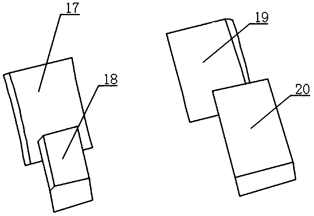
[0042] Such as figure 1 with image 3 As shown, this embodiment is based on Embodiment 1, the first ratchet shifting sleeve 9 includes a first connecting sleeve 17 and a first shifting block 18, and the first shifting block 18 is connected to the first shifting block 18. A connecting sleeve 17 is fixedly connected, and the first connecting sleeve 17 is fixedly sleeved outside the hand relief sliding sleeve 8, and the first toggle block 18 protrudes from the sliding groove and is slidably connected with the sliding groove ; The second ratchet shifting sleeve 10 includes a second connecting sleeve 19 and a second shifting block 20, the second shifting block 20 is fixedly connected with the second connecting sleeve 19, and the second connecting sleeve 19 is fixedly sleeved on the outside of the hand relief sliding sleeve 8, and the second toggle block 20 protrudes from the sliding groove and is slidably connected with the sliding groove.

[0043] The second shifting block 20 an...


PUM


Abstract

The invention discloses a hand relieving mechanism of a parking braking cylinder. The hand relieving mechanism of the parking braking cylinder is arranged on a cylinder cover of the parking braking cylinder; the hand relieving mechanism of the parking braking cylinder comprises a hand relieving body, a pawl, a ratchet wheel bush, a first hand relieving spring, a second hand relieving spring, a hand relieving sliding sleeve, a first pawl shifting sleeve and a second pawl shifting sleeve; the ratchet wheel bush is rotationally connected to the cylinder cover; the pawl is rotationally connected to the cylinder cover through a pawl shaft; and one end of the pawl is matched with a toothed groove in the ratchet wheel bush. According to the hand relieving mechanism of the parking braking cylinder, by arranging the first pawl shifting sleeve and the second pawl shifting sleeve, the use of a torsion spring is avoided; and therefore, a problem of failure caused by too long use time brought by the torsion spring is solved; the detaching is convenient during overhauling; it only needs to detect wear capacity of a pawl rotating internal hole, two contacts, the first pawl shifting sleeve and thesecond pawl shifting sleeve; and the workload during overhauling is reduced.

Description

technical field [0001] The invention relates to the technical field of rail vehicle braking, in particular to a hand release mechanism for parking a brake cylinder. Background technique [0002] Common forms of foundation braking devices for rail vehicles include: a tread brake unit that obtains braking force by pressing the tread and a brake caliper unit that obtains braking force by clamping the brake disc. The application and release of its service brake is usually realized by using compressed air: the service brake is applied when the compressed air is charged; the service brake is released when the compressed air is discharged. In order to ensure the parking requirements of the vehicle under windless conditions (such as parking in the garage at night, the vehicle air compressor does not work, and the vehicle has no wind pressure), the foundation braking device is usually designed with a parking brake mechanism, which usually includes a spring The energy storage mechani...

Claims


Application Information

Patent Timeline
Patent Type & Authority Applications(China)
IPC IPC(8): B61H13/02
CPCB61H13/02
Inventor 陈俊杰赵志成洪应昌姜永明曾地明
Owner 四川江山轨道交通装备制造有限公司
Why Eureka
Try Eureka