
Highway roadbed abutment backfilling gravel inverted filter layer pavement device

A technology of reverse filter layer and roadbed, which is applied in the direction of filters, roads, roads, etc., can solve the problems of high labor cost, large construction randomness of workers, and unqualified quality of reverse filter layer, so as to facilitate maintenance and replacement and reduce sharing cost, cost reduction effect

Pending Publication Date: 2019-07-05
THE THIRD ENG CO LTD OF CCCC SECOND HIGHWAY ENG BUREAU
View PDF0 Cites 0 Cited by
  • Summary
  • Abstract
  • Description
  • Claims
  • Application Information

AI Technical Summary

Problems solved by technology

[0002] In the process of highway construction, it is necessary to monitor the paving quality of the backfill anti-filter layer on the back of the roadbed under construction. At present, the commonly used method is to pave manually with shovels, which consumes relatively high labor costs, and the construction of workers is relatively random. Large, it is difficult to ensure the thickness and width of the pavement during the construction process. There are many super-sized materials in the material, and workers may not be able to clean up all the super-sized materials. The unqualified materials and construction specifications lead to construction failures. If the quality of the reverse filter layer is unqualified, it will affect the overall drainage function of the subgrade

Method used


Image

  • Highway roadbed abutment backfilling gravel inverted filter layer pavement device
  • Highway roadbed abutment backfilling gravel inverted filter layer pavement device
  • Highway roadbed abutment backfilling gravel inverted filter layer pavement device

Examples


Embodiment Construction

[0020] The present invention will be clearly and completely described below in conjunction with the accompanying drawings, so that those skilled in the art can fully implement the present invention without creative work.

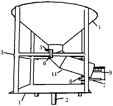
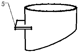
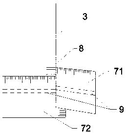
[0021] The specific embodiment of the present invention is: as Figure 1-6 As shown, a paving device for backfilling gravel reverse filter layer on the back of road subgrade platform includes a main frame 3, a bottom plate 1, a hopper 4, a diversion pipe 11, a limiter 7, a flow regulating plate 5, a walking wheel 2, a sieve plate 10, the main frame 3 is arranged above the bottom plate 1, the main frame 3 includes a main frame and a balance frame, the hopper 4 is arranged on the main frame 3, and the traveling wheels 2 are arranged at the bottom of the bottom plate 1, and the The guide tube 11 is arranged at the bottom of the hopper 4, and the guide tube 11 includes vertical tubes, corners and oblique tubes from top to bottom. The notch is inserted, and the ...


PUM


Abstract

The invention provides a highway roadbed abutment backfilling gravel inverted filter layer pavement device. A main frame, a bottom plate, a hopper, a flow guiding pipe, a limiter, a flow adjusting plate, walking wheels and a sieve plate are included. The main frame is arranged above the bottom plate and comprises a main framework and a balance frame. The hopper is arranged on the main frame. The walking wheels are arranged at the bottom of the bottom plate. The flow guiding pipe is arranged at the bottom of the hopper. The flow guiding pipe comprises a vertical pipe, a corner and an inclined pipe from top to bottom. A notch is formed in the side portion of the vertical pipe. The flow adjusting plate is inserted in the notch, falling material flow is adjusted through drawing, and the corneris connected with the vertical pipe and the inclined pipe. The outlet end of the inclined pipe is arranged on the right side of the bottom plate. The sieve plate is arranged in the hopper and provided with a plurality of sieve holes. The limiter comprises a longitudinal limiting plate and a transverse limiting plate, and is fixed to the right side of the main frame through a clamping piece. The highway roadbed abutment backfilling gravel inverted filter layer pavement device is simple in structure and convenient to disassemble and assemble, pavement materials are subjected to pavement throughthe limiter, and the effect is conveniently achieved.

Description

technical field [0001] The invention belongs to the technical field of road construction equipment, and in particular relates to a paving device for backfilling a gravel reverse filter layer on the back of a road bed abutment. Background technique [0002] In the process of highway construction, it is necessary to monitor the paving quality of the backfill anti-filter layer on the back of the roadbed under construction. At present, the commonly used method is to pave manually with shovels, which consumes relatively high labor costs, and the construction of workers is relatively random. Large, it is difficult to ensure the thickness and width of the pavement during the construction process. There are many super-sized materials in the material, and workers may not be able to clean up all the super-sized materials. The unqualified materials and construction specifications lead to construction failures. If the quality of the reverse filter layer is unqualified, it will affect th...

Claims


Application Information

Patent Timeline
Patent Type & Authority Applications(China)
IPC IPC(8): B07B1/04B07B1/46E01C19/00E01C19/20
CPCB07B1/04B07B1/46E01C19/00E01C19/20E01C2019/207
Inventor 贾晓博
Owner THE THIRD ENG CO LTD OF CCCC SECOND HIGHWAY ENG BUREAU
Learn More