Movable all-round control jujube hitting machine
An all-round, jujube machine technology, applied in the direction of picking machines, harvesters, agricultural machinery and implements, etc., can solve the problems of unreasonable structure, high work efficiency, troublesome use, etc., and achieve stable structure, simple structure and convenient use Effect
- Summary
- Abstract
- Description
- Claims
- Application Information
AI Technical Summary
Problems solved by technology
Method used
Image
Examples
Embodiment 1
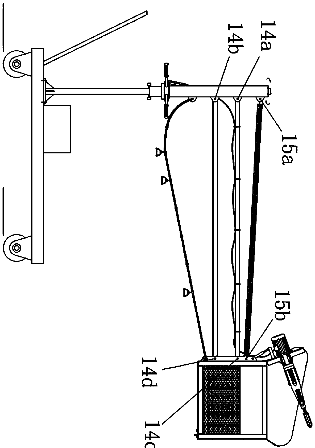
[0027] Embodiment 1: a kind of as figure 1 The jujube punching machine shown involves main components: base 1, universal wheel 2, support rod 4, rotating tube 9, upper swing rod 11, lower swing rod 12, extension spring 10, traction rope 13, lifting frame 32, hopper 16 , motor 17, centrifugal head shaker 20 and power supply etc. Wherein, the universal wheel 2 is installed at the bottom of the base 1 to realize the function of free movement on the ground, and the push-pull rod 3 is installed on the upper side of the base 1, and the base 1 is controlled to move by the push-pull rod 3. And a universal wheel brake structure (prior art) is provided to keep the base 1 fixed in place. A support rod 4 is vertically fixed on the top surface of the base 1 , and the support rod 4 may be located in the middle of the base 1 , and is usually fixed on one side of the base 1 .
[0028] Swivel frame is housed on the support bar 4, in the present embodiment, as Figure 7 The shown swivel fram...
Embodiment 2
[0035] Embodiment 2: On the basis of the above embodiment 1, the mode for controlling the swing angle of the motor and the centrifugal head 20 can also be adopted such as Figure 9 shown in the knob structure, the Figure 9 Among them, the knob used is a helical tube with threads at both ends and opposite thread directions, the outer side of the helical tube is welded with a handle, the two ends of the helical tube are respectively equipped with screw rods, and the two ends of the screw rods are respectively hinged on the lifting frame 32 and the motor holder.
Embodiment 3
[0036] Embodiment 3: On the basis of Embodiment 1, the lifting frame 32 and the hopper 16 are movably installed and can be disassembled. The structure can be as follows: Figure 8 The connection relationship shown is that an inclined downward notch is provided on the side of the lifting frame 32 as a card slot, and a plurality of corresponding clips are provided on the side of the hopper 16, and each clip is matched and mounted on the corresponding clip slot Among them, the inward movement of the chuck along the slope of the slot can keep the two firmly connected, and a fixing bolt can further be connected between the hopper 16 and the lifting frame 32 .
PUM
 Abstract
Description
Claims
Application Information
 - R&D
- Intellectual Property
- Life Sciences
- Materials
- Tech Scout
- Unparalleled Data Quality
- Higher Quality Content
- 60% Fewer Hallucinations
Browse by: Latest US Patents, China's latest patents, Technical Efficacy Thesaurus, Application Domain, Technology Topic, Popular Technical Reports.
© 2025 PatSnap. All rights reserved.Legal|Privacy policy|Modern Slavery Act Transparency Statement|Sitemap|About US| Contact US: help@patsnap.com


