


Quick Research
Generate reliable direction feasibility study reports for your R&D in just a few steps.

Technical Q&A
Discover and master advanced knowledge NOW. Basics, ideas, possibilities, all at once.

Find Solutions
As an expert in R&D theories, this can generate solutions to your technical problems instantly.

Evaluate Feasibility
Analyze your overall solution with one click, know your potential R&D risks in advance.

Monitor Landscape
Get weekly tech updates, stay abreast of the latest tech innovations and key insights.
Manufacturing method of precision forging machine hammer bar
A production method and precision forging machine technology, applied in the field of forging machinery, can solve the problems of high processing cost, irreparable, long cycle, etc., and achieve the effect of low processing cost and suitable production process route
- Summary
- Abstract
- Description
- Claims
- Application Information
AI Technical Summary
Problems solved by technology
Method used
Image

Examples
Embodiment 1
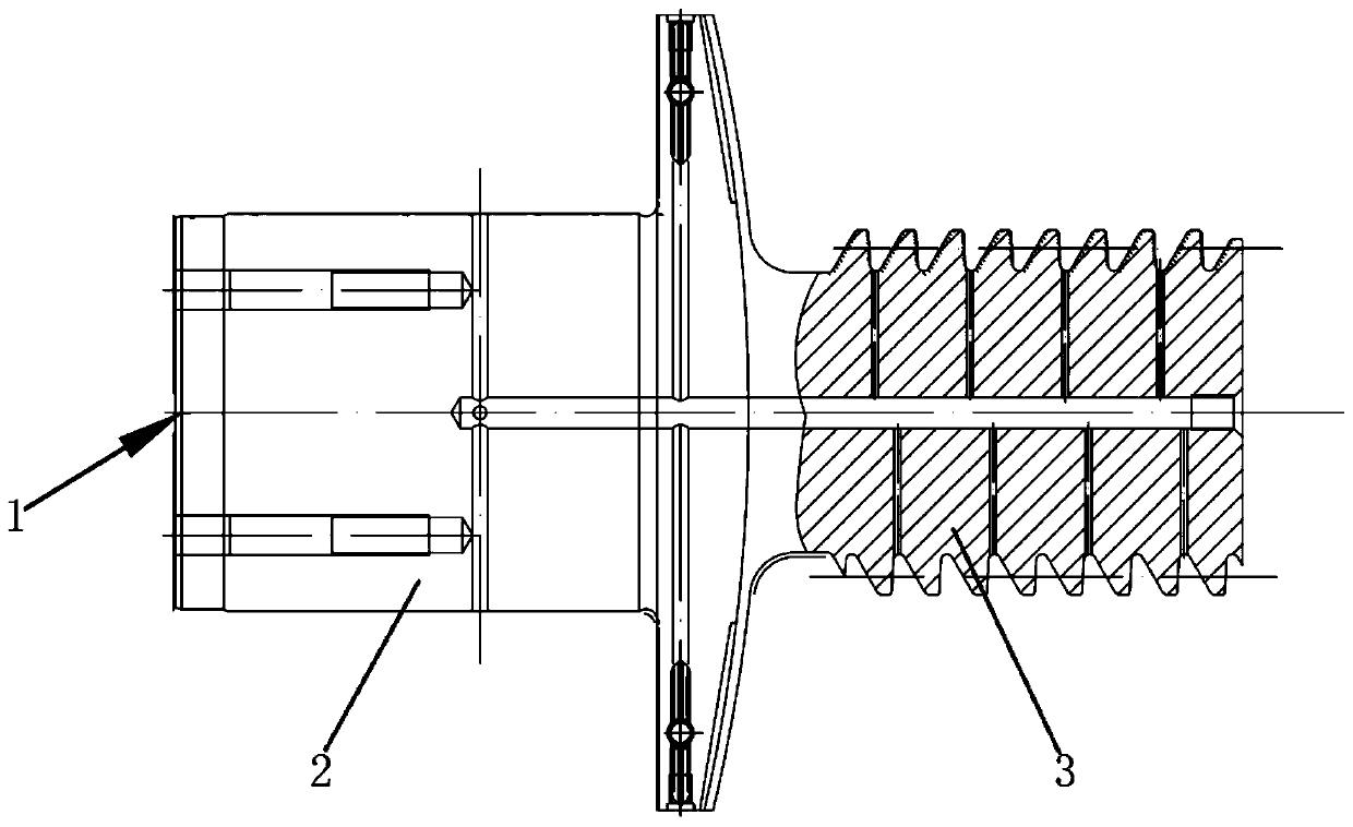
[0065] The scrapped SKK precision forging machine hammer rod was redesigned, modified and reused. According to the split design structure, the forged end of the hammer rod was Φ180mm according to the requirements of the drawing, and the cylinder was turned to Φ100mm tolerance (+0.02~+0.04), and the height of the cylinder was 121mm tolerance (﹣ 0.1~0);
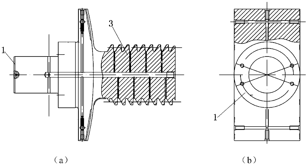
[0066] Machining the hammer backing ring and the hammer base, such as image 3 As shown, four threads M10X1 are tightly connected, and the material, structure and size of the thread end remain unchanged; the material of the hammer backing ring is 30CrNiMo8, and the material of the hammer cap is VIDAR forged. The forging times are not less than three pulls and three pulls. There must be no white spots, cracks and defects that affect the performance of the material, and a flaw detection report is issued, and the raw material is quenched and tempered: HRC34-38; the hammer backing ring is processed according to the structure and si...
Embodiment 2
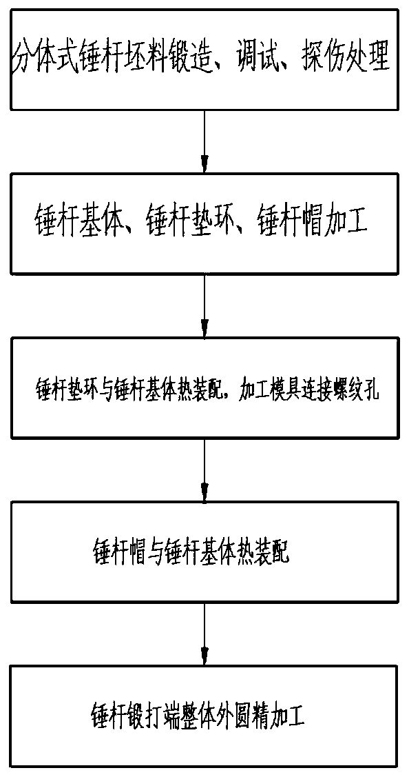
[0072] The hammer rod of the new SKK precision forging machine is designed according to the split structure. The material of the hammer rod base, the hammer rod backing ring is 30CrNiMo8, and the material of the hammer rod cap is VIDAR. The forging times are not less than three pulls and three pulls. Points, cracks and defects that affect material performance, flaw detection and issue a flaw detection test report;
[0073] Quenching and tempering treatment of raw materials: HRC34-38; process the hammer backing ring and hammer cap according to the structure and size design requirements of the hammer base, hammer backing ring and hammer cap. Hammer base image 3 The shown semi-finishing leaves a finishing allowance of 0.5mm, then vacuum heat-treats HRC48±2, and finally finishes the hammer base. The thread B165X22 is processed in accordance with the DIN513 (ISO5855) standard to ensure that the forged end cylinder has a tolerance of Φ100mm (+0.02~+ 0.04), cylinder height 121mm to...
PUM
 Abstract
Description
Claims
Application Information
 - R&D Engineer
- R&D Manager
- IP Professional
- Industry Leading Data Capabilities
- Powerful AI technology
- Patent DNA Extraction
Browse by: Latest US Patents, China's latest patents, Technical Efficacy Thesaurus, Application Domain, Technology Topic, Popular Technical Reports.
© 2024 PatSnap. All rights reserved.Legal|Privacy policy|Modern Slavery Act Transparency Statement|Sitemap|About US| Contact US: help@patsnap.com