Fanless Water Cooling Industrial Ethernet Switch

A water-cooled heat dissipation, Ethernet technology, applied in the direction of cooling/ventilation/heating transformation, chassis/cabinet/drawer parts, etc., can solve the problems of poor heat dissipation effect, poor operating environment, and increase the difficulty of industrial Ethernet switches. , to achieve the effect of improving heat dissipation and increasing safety

Active Publication Date: 2020-12-25
深圳市光路在线科技有限公司
View PDF5 Cites 0 Cited by
  • Summary
  • Abstract
  • Description
  • Claims
  • Application Information

AI Technical Summary

Problems solved by technology

[0003] Existing industrial Ethernet switches have certain disadvantages during use. Traditional industrial Ethernet switches are designed with an air-cooled heat dissipation structure, which makes the traditional air-cooled structure generate certain wind noise during operation. Long-term exposure is harmful to the use of The hearing of the patient is affected to a certain extent. Traditional air-cooled heat dissipation consumes a lot of energy, and the heat dissipation effect is poor. The operating environment of traditional industrial Ethernet switches is poor, making industrial Ethernet switches prone to internal dust accumulation during long-term use. Phenomenon, which has a certain impact on the operation of industrial Ethernet switches. The disassembly operation of traditional industrial Ethernet switches is laborious, which increases the difficulty of maintenance of industrial Ethernet switches. Industrial Ethernet switches themselves do not have network cable locks, making network cable connectors It is easy to fall off under the action of external force, which will bring certain adverse effects to users

Method used


Image

  • Fanless Water Cooling Industrial Ethernet Switch
  • Fanless Water Cooling Industrial Ethernet Switch
  • Fanless Water Cooling Industrial Ethernet Switch

Examples


Embodiment Construction

[0034] The technical solutions in the embodiments of the present invention will be clearly and completely described below in conjunction with the embodiments of the present invention. Apparently, the described embodiments are only some of the embodiments of the present invention, not all of them. Based on the embodiments of the present invention, all other embodiments obtained by persons of ordinary skill in the art without creative efforts fall within the protection scope of the present invention.

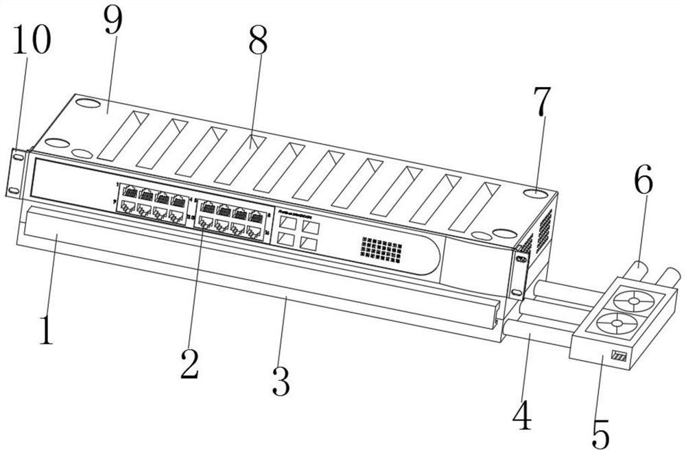
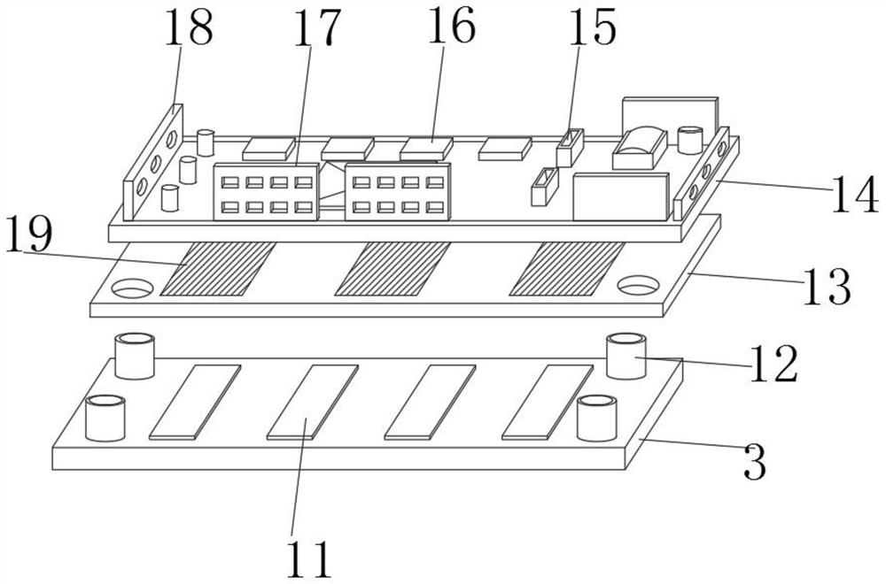
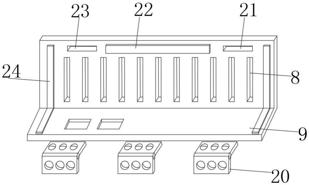
[0035] Such as Figure 1-7 As shown, the fanless water-cooled heat dissipation industrial Ethernet switch includes a folded flip cover 9, an original bottom plate 14, a splicing base 3, a water pump shell 5, a sliding card plate 28, a sealed pump part 31, a limit buckle plate 47, and a wiring slot 2 With the mobile corner buckle 39, the double-fold flip cover 9 is movably installed on the upper outer surface of the splicing base 3, and the double-fold flip cover 9 and the splicing...


PUM


Abstract

The invention discloses a fan-free water-cooling heat-radiation industrial Ethernet switch which comprises a doubling cover, an original base plate, a splicing pedestal, a water pump protective casing, a sliding clamping plate, a sealing pump member, a limiting buckle plate, a butt-joint wire duct and a movable corner buckle, the doubling cover is movably mounted in the outer surface of the upperend of the splicing pedestal, and is joint and fixed to the splicing pedestal via three rotary hinges, top air ducts are formed in the inner side of the doubling cover in a penetrating way, compactingclamping strips are fixedly mounted close to the two sides of the air ducts in the external surface of the doubling cover, and a compacting pad is fixedly mounted close to the upper middle position of the top air ducts in the external surface of the doubling cover. According to the fan-free water-cooling heat-radiation industrial Ethernet switch, the water-cooling and heat radiation safety of theEthernet switch are improved, maintenance and operation of the Ethernet switch are more convenient, the switch itself includes a dust removing structure, the service life of the switch is prolonged,a network cable joint can be inserted more firmly, and better using experience is provided.

Description

technical field [0001] The invention belongs to the technical field of network equipment, and in particular relates to an Ethernet switch, more specifically a fanless water-cooled industrial Ethernet switch. Background technique [0002] The Ethernet switch is a switch based on Ethernet to transmit data. Ethernet adopts a local area network of shared bus transmission media. The structure of the Ethernet switch is that each port is directly connected to the host, and generally works in full-duplex mode. The switch can connect many pairs of ports at the same time, so that each pair of hosts that communicate with each other can transmit data without conflict as if they are exclusive to the communication medium. Ethernet switches work on the second layer of the OSI network reference model, the data link layer. Media access control, address identification completes the network equipment of Ethernet data frame forwarding; [0003] Existing industrial Ethernet switches have certai...

Claims


Application Information

Patent Timeline
Patent Type & Authority Patents(China)
IPC IPC(8): H05K7/20H05K5/02
Inventor 不公告发明人
Owner 深圳市光路在线科技有限公司
Why Eureka
Try Eureka