A walking driving mechanism for a pipeline robot

A pipeline robot and walking drive technology, applied in the field of intelligent robots, can solve problems affecting the stability and reliability of pipeline robot equipment, poor control accuracy, lack of diversion and diversion establishment, etc., to achieve good walking ability and environmental adaptability , improve safety and reliability, and avoid damage to the traveling mechanism

Active Publication Date: 2020-07-31
JIAOZUO UNIV
View PDF5 Cites 0 Cited by
  • Summary
  • Abstract
  • Description
  • Claims
  • Application Information

AI Technical Summary

Problems solved by technology

[0002] At present, the walking mechanism used by the pipeline inspection robot is often the traditional drive motor directly connected to the road wheel and the pipeline robot body, or the drive motor is connected to the road wheel and the pipeline robot body through a structure such as a gear box, a transmission shaft, etc. It meets the needs of driving pipeline robots. Although this structure can meet the needs of use to a certain extent, on the one hand, the current running mechanism of this type lacks flow diversion and diversion during operation, so it is very easy for the walking wheels to be affected by the inside of the pipeline during operation. Liquid, gas and other medium obstructions, large running resistance and poor running direction control stability, resulting in the common defects of running wheels such as large running energy consumption and running wear and poor control accuracy, and relatively poor environmental adaptability. In addition, the current The walking structure of the pipeline inspection robot lacks independent environment detection and obstacle avoidance capabilities, and needs to rely on the obstacle avoidance device located on the pipeline robot body for guidance and control, resulting in a large number of dead ends in the detection of the walking path during the walking process, which is very easy to detect due to Insufficient identification leads to the failure or damage of the walking mechanism due to impact, jamming, etc., which seriously affects the stability and reliability of the pipeline robot equipment. Therefore, in view of this situation, it is urgent to develop a new pipeline robot walking mechanism , to meet the needs of practical use

Method used


Image

  • A walking driving mechanism for a pipeline robot
  • A walking driving mechanism for a pipeline robot

Examples


Embodiment Construction

[0019] In order to make the technical means, creative features, goals and effects achieved by the present invention easy to understand, the present invention will be further described below in conjunction with specific embodiments.

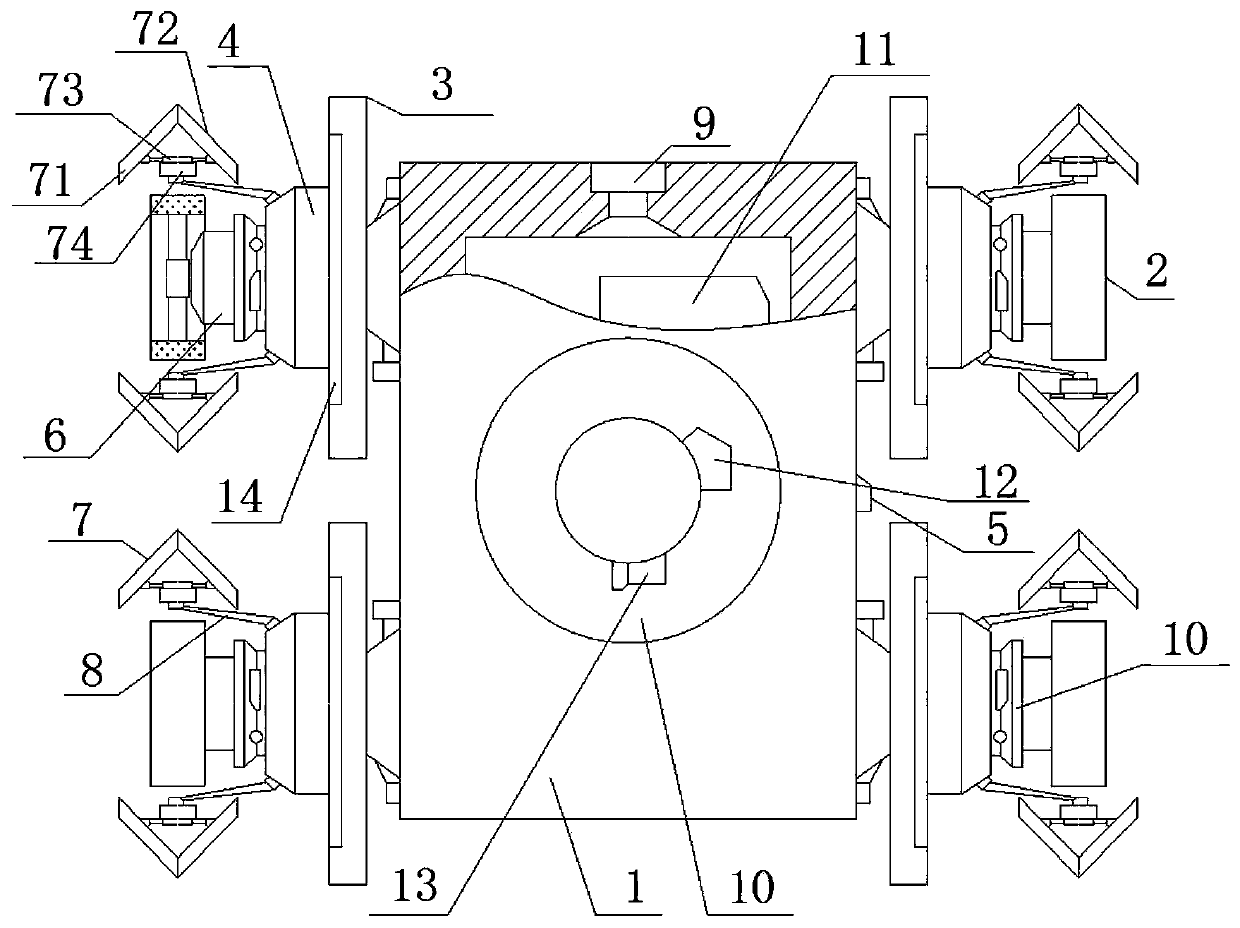
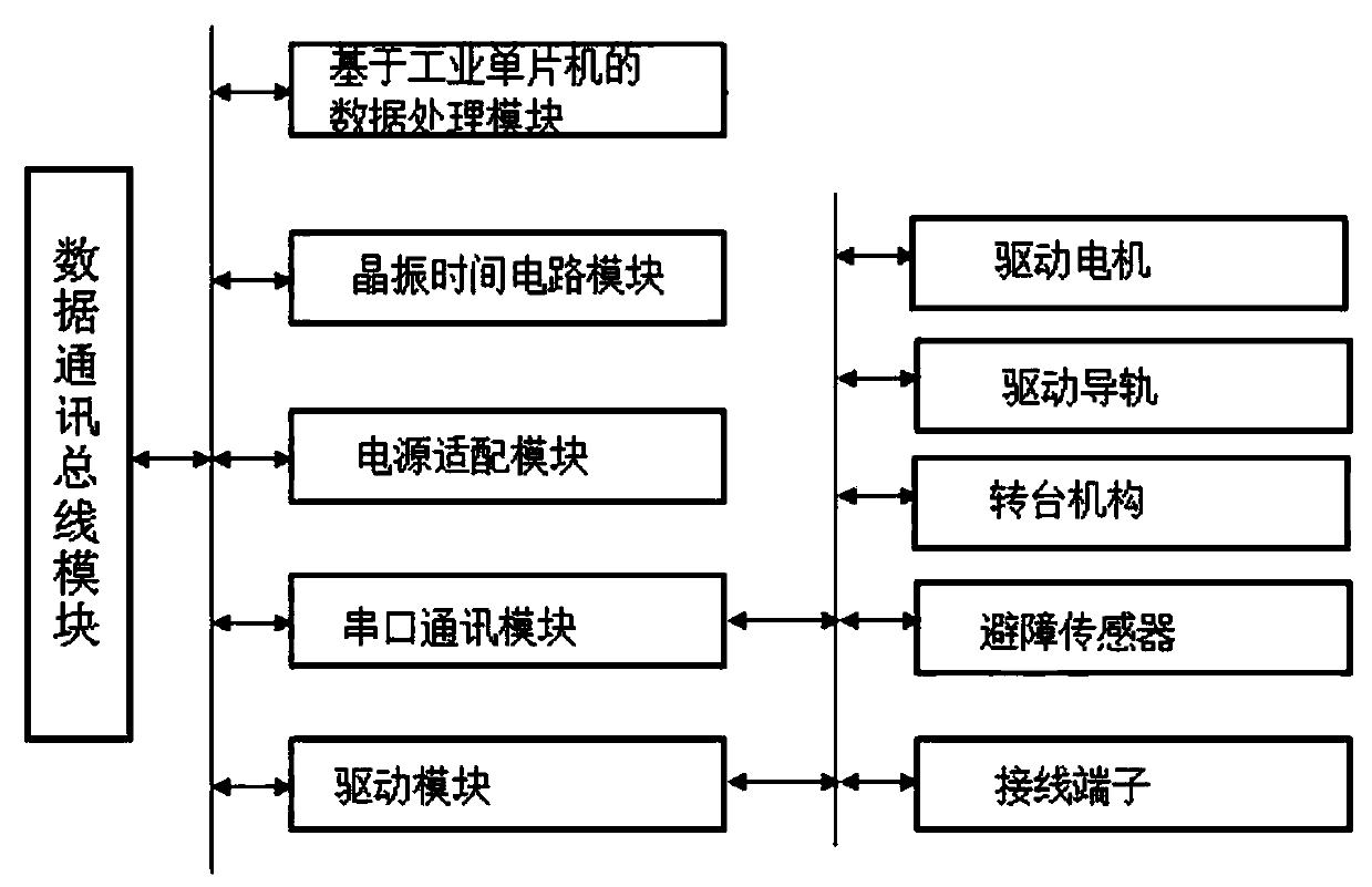
[0020] Such as figure 1 with 2 The walking driving mechanism for a pipeline robot includes a bearing base 1, a walking wheel 2, a driving guide rail 3, a slider 4, a driving motor 6, a splitter plate 7, a bearing column 8, an obstacle avoidance sensor 9, and a turntable mechanism 10 And the control system 11, the carrying base 1 is a closed cavity structure with a rectangular cross section, the control system 11 is embedded in the carrying base 1 and is electrically connected with the driving guide rail 3, the driving motor 6, the obstacle avoidance sensor 9, and the turntable mechanism 10 , there are at least two driving guide rails 3, which are symmetrically distributed on both sides of the bearing base 1 with the axis of the bearing base 1, hi...


PUM


Abstract

The invention relates to a walking drive mechanism for a pipeline robot. The walking drive mechanism for the pipeline robot comprises a bearing base, a bearing stand column, a bearing table, a workingtable, a first horizontal line rail, a second horizontal line rail, a third horizontal line rail, a vertical line rail, a working machine head, a rotary table mechanism, auxiliary drive columns and acontrol circuit, wherein the upper end surface of the base is slidably connected with the bearing table through the first horizontal line rail; the upper end surface of the bearing plate is connectedwith the rotary table mechanism through the second horizontal line rail; the upper end surface of the rotary table mechanism is connected with the lower end surface of the working table; the auxiliary drive columns are uniformly distributed at the position between the working table and the bearing base around the axis of the rotary table mechanism; and the control circuit is located on the outersurface of the bearing base. According to the walking drive mechanism for the pipeline robot provided by the invention, on one hand, the requirement on processing workpieces in different weights, withdifferent structures and in different working surfaces can be effectively met, on the other hand, the integral structural strength of a vertical machining center can be effectively improved, and therequirement of the vertical machining center on effectively bearing and positioning irregular workpieces with large volumes and large dead weights is effectively met.

Description

technical field [0001] The invention relates to a walking mechanism, belonging to the technical field of intelligent robots. Background technique [0002] At present, the walking mechanism used by the pipeline inspection robot is often the traditional drive motor directly connected to the road wheel and the pipeline robot body, or the drive motor is connected to the road wheel and the pipeline robot body through a structure such as a gear box, a transmission shaft, etc. It meets the needs of driving pipeline robots. Although this structure can meet the needs of use to a certain extent, on the one hand, the current running mechanism of this type lacks flow diversion and diversion during operation, so it is very easy for the walking wheels to be affected by the inside of the pipeline during operation. Liquid, gas and other medium obstructions, large running resistance and poor running direction control stability, resulting in the common defects of running wheels such as large ...

Claims


Application Information

Patent Timeline
Patent Type & Authority Patents(China)
IPC IPC(8): F16L55/40F16L55/32F16L101/30
Inventor 司国斌张艳王翠芳孙备李鸿征白玲司雁梅
Owner JIAOZUO UNIV
Why Eureka
Try Eureka