Microphone for communication

The technology of a microphone and the other side, applied in the field of microphones, can solve the problems of poor anti-drop performance, inconvenient use, and easy damage, and achieve the effects of strong anti-drop performance, convenient use and high applicability

Inactive Publication Date: 2019-06-25
滑迪
View PDF1 Cites 0 Cited by
  • Summary
  • Abstract
  • Description
  • Claims
  • Application Information

AI Technical Summary

Problems solved by technology

[0002] A microphone is a transducer that converts sound into electrical signals. With the rapid development of electronic technology in recent years, microphones have also been widely used in electronic equipment. In the field of communication, microphones are necessary equipment. After retrieval , the Chinese patent authorization number is CN 203691585U, which discloses a microphone, including a circuit board and a casing packaged as one, and a diaphragm, a gasket and a pole are arranged in sequence in the space enclosed by the circuit board and the casing. Plate, the diaphragm is close to the bottom of the shell, and the pole plate and the circuit board are electrically connected through a conductive part; an insulating cavity is surrounded between the pole plate and the shell, and the conductive part includes a platform that abuts against the plane of the pole plate. The microphone in the patent has low applicability in the field of communication. When in use, it cannot be disassembled according to the needs. It is inconvenient to use, and has poor anti-drop performance, and it is prone to damage when dropped.

Method used


Image

  • Microphone for communication
  • Microphone for communication

Examples


Embodiment Construction

[0017] The following will clearly and completely describe the technical solutions in the embodiments of the present invention with reference to the accompanying drawings in the embodiments of the present invention. Obviously, the described embodiments are only some, not all, embodiments of the present invention.

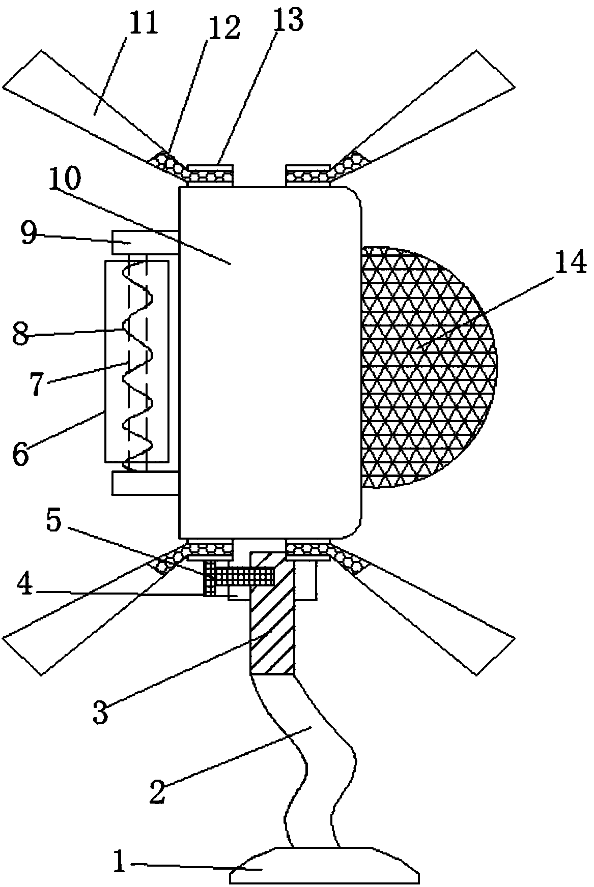
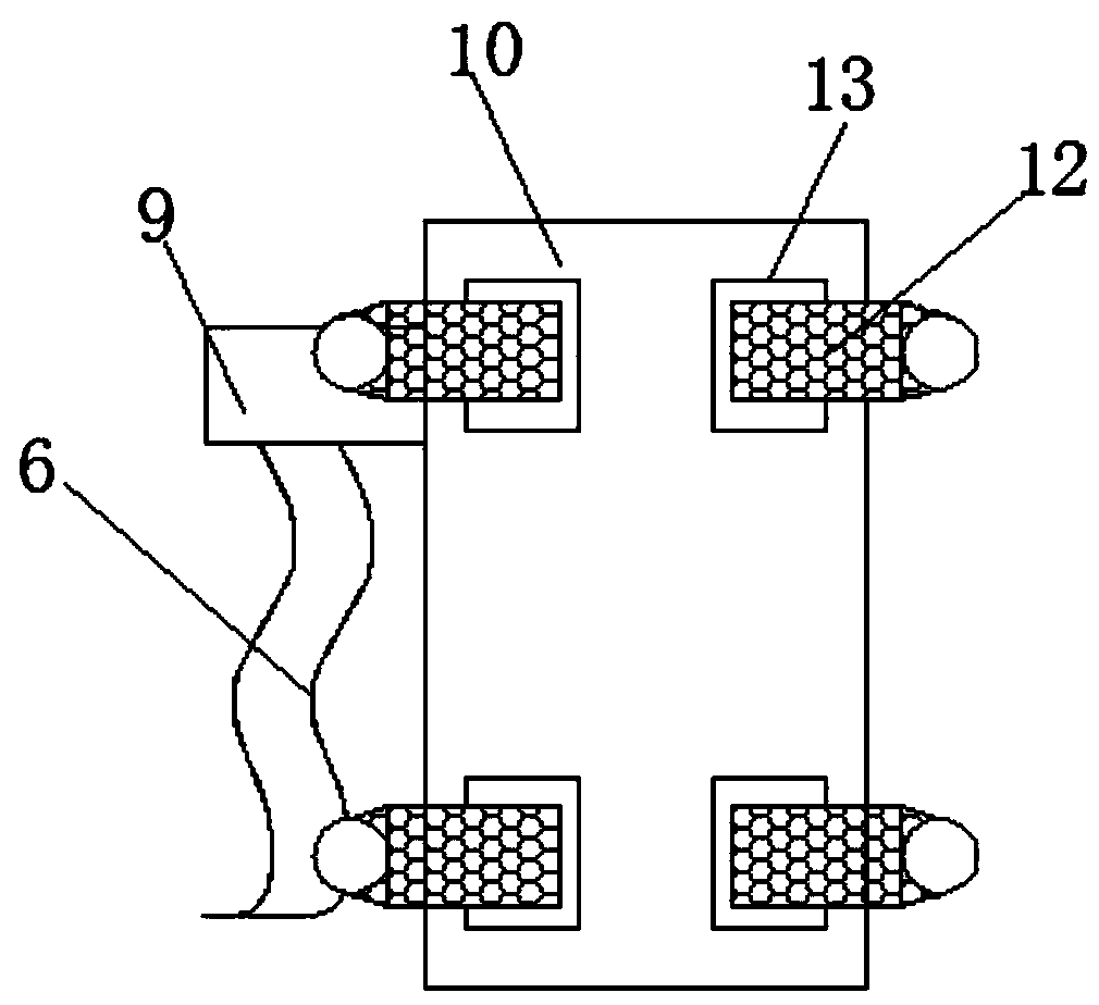
[0018] refer to Figure 1-2 , a microphone for communication, comprising a microphone body 10, the middle of the outer wall of the bottom end of the microphone body 10 protrudes outward to form a card slot 4, one side of the outer wall of the card slot 4 is provided with a threaded hole, and the inner wall of the threaded hole is threaded. Tighten the bolt 5, and one end of the fastening bolt 5 extends to the inside of the slot 4, the inside of the slot 4 is fixed with a vertically arranged connecting column 3 through the fastening bolt 5, and the outer wall of the bottom end of the connecting column 3 is welded with a metal The universal tube 2, the bottom end of th...


PUM


Abstract

The invention discloses a microphone for communication comprising a microphone body. The middle of the outer wall of the bottom end of the microphone body protrudes outwards to form a clamping groove.A threaded hole is formed in the outer wall of one side of the clamping groove; the inner wall of the threaded hole is in threaded connection with a fastening bolt; one end of the fastening bolt extends into the clamping groove. A vertically-arranged connecting column is fixed in the clamping groove through a fastening bolt, a metal universal pipe is welded to the outer wall of the bottom end ofthe connecting column, a supporting base is clamped to the bottom end of the metal universal pipe, and mounting bases with inserting grooves are welded to the four corners of the top end and the fourcorners of the bottom end of the microphone body. Through the arrangement of the rubber rods, when the novel falling-off device falls off to the ground, the rubber rods can be bent to reduce impact force, through protection of the eight rubber rods, the novel falling-off device can prevent the novel falling-off device from being damaged, the protection performance and the falling-off resistance are high, the novel falling-off device can be changed according to needs, and the novel falling-off device is more convenient and faster to use and higher in applicability.

Description

technical field [0001] The invention relates to the technical field of microphones, in particular to a communication microphone. Background technique [0002] A microphone is a transducer that converts sound into electrical signals. With the rapid development of electronic technology in recent years, microphones have also been widely used in electronic equipment. In the field of communication, microphones are necessary equipment. After retrieval , the Chinese patent authorization number is CN 203691585U, which discloses a microphone, including a circuit board and a casing packaged as one, and a diaphragm, a gasket and a pole are arranged in sequence in the space enclosed by the circuit board and the casing. Plate, the diaphragm is close to the bottom of the shell, and the pole plate and the circuit board are electrically connected through a conductive part; an insulating cavity is surrounded between the pole plate and the shell, and the conductive part includes a platform th...

Claims


Application Information

Patent Timeline
Patent Type & Authority Applications(China)
IPC IPC(8): H04R1/08
Inventor 滑迪
Owner 滑迪
Why Eureka
Try Eureka