Magnetic monopole motor
A magnetic monopole and electromagnetic technology, applied in electrical components, electromechanical devices, electric components, etc., can solve the problems of narrow application fields of traditional magnetic monopole motors, and achieve the effects of light weight, high reliability and wide application range.
- Summary
- Abstract
- Description
- Claims
- Application Information
AI Technical Summary
Problems solved by technology
Method used
Image


Examples
Embodiment 1
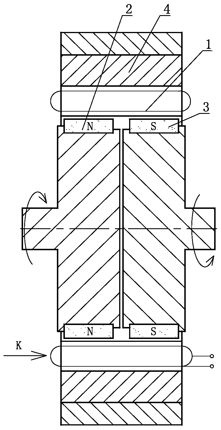
[0047] A magnetic unipolar motor such as figure 1 As shown, it includes a conductor 1, an N pole circumferential magnetic monopole 2 and an S pole circumferential magnetic monopole 3, the conductor 1 is arranged on an electromagnetic counterpart 4, and the N pole circumferential magnetic monopole 2 It is arranged corresponding to the conductor 1 , and the S-pole circumferential magnetic monopole 3 is arranged corresponding to the conductor 1 .
Embodiment 2
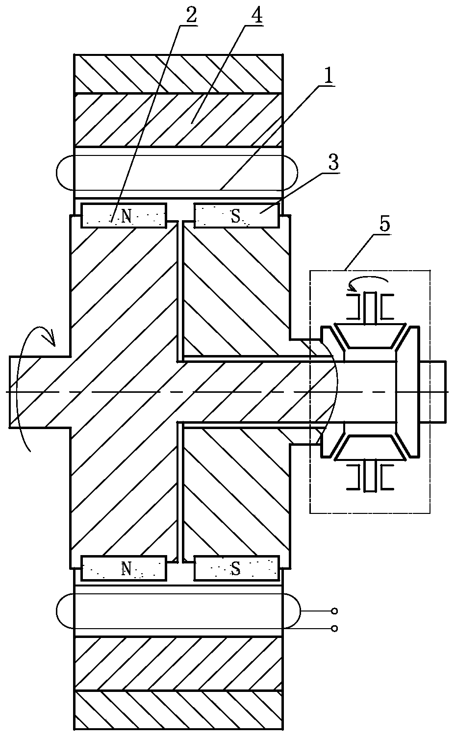
[0049]A magnetic unipolar motor such as figure 2 As shown, it includes a conductor 1, an N pole circumferential magnetic monopole 2 and an S pole circumferential magnetic monopole 3, the conductor 1 is arranged on an electromagnetic counterpart 4, and the N pole circumferential magnetic monopole 2 Corresponding to the conductor 1, the S pole circumferential magnetic monopole 3 is disposed corresponding to the conductor 1, the N pole circumferential magnetic monopole 2 and the S pole circumferential magnetic monopole 3 Set through mechanical mechanism 5 reverse linkage.
[0050] As an alternative embodiment, in Embodiment 2 of the present invention, the mechanical mechanism 5 can be further selectively configured as a bevel gear planetary mechanism.
Embodiment 3
[0052] A magnetic unipolar motor such as image 3 As shown, it includes a conductor 1, an N pole circumferential magnetic monopole 2 and an S pole circumferential magnetic monopole 3, the conductor 1 is arranged on an electromagnetic counterpart 4, and the N pole circumferential magnetic monopole 2 Corresponding to the conductor 1, the S-pole circumferential magnetic monopole 3 is disposed corresponding to the conductor 1, the N-pole circumferential magnetic monopole 2 is fixedly connected to the forward-rotating compressor blade 41, and the The S-pole circumferential magnetic monopole 3 is fixedly connected to the counter-rotating compressor blade 42 .
PUM
 Abstract
Description
Claims
Application Information
 - R&D
- Intellectual Property
- Life Sciences
- Materials
- Tech Scout
- Unparalleled Data Quality
- Higher Quality Content
- 60% Fewer Hallucinations
Browse by: Latest US Patents, China's latest patents, Technical Efficacy Thesaurus, Application Domain, Technology Topic, Popular Technical Reports.
© 2025 PatSnap. All rights reserved.Legal|Privacy policy|Modern Slavery Act Transparency Statement|Sitemap|About US| Contact US: help@patsnap.com