
Spinning frame drafting device based on textile

A drafting device and spinning frame technology, applied in spinning machines, drafting equipment, textiles and papermaking, etc., can solve the problems of no stabilizing device facilities, harsh factory environment, no anti-skid measures, etc., to optimize the working environment of workers, Reduce production cost and prevent internal fiber breakage

Inactive Publication Date: 2019-06-25
江苏世恒织造有限公司
View PDF10 Cites 1 Cited by
  • Summary
  • Abstract
  • Description
  • Claims
  • Application Information

AI Technical Summary

Problems solved by technology

[0003] However, there are more or less problems in the products on the market. First, the traditional drafting device does not have a device for squeezing and leveling the spun yarn to prevent the spun yarn from breaking during drafting. Second, there is no Shock absorbing device, the motor emits huge vibrations during use, causing it to produce a huge roar, making the factory environment harsh. Third, there is no facility to stabilize the entire device, and redundant brackets are often needed for support during use. Fourth, When the spun yarn is wound on the spindle, there is no anti-slip measure, causing the spun yarn to slip and be polluted

Method used

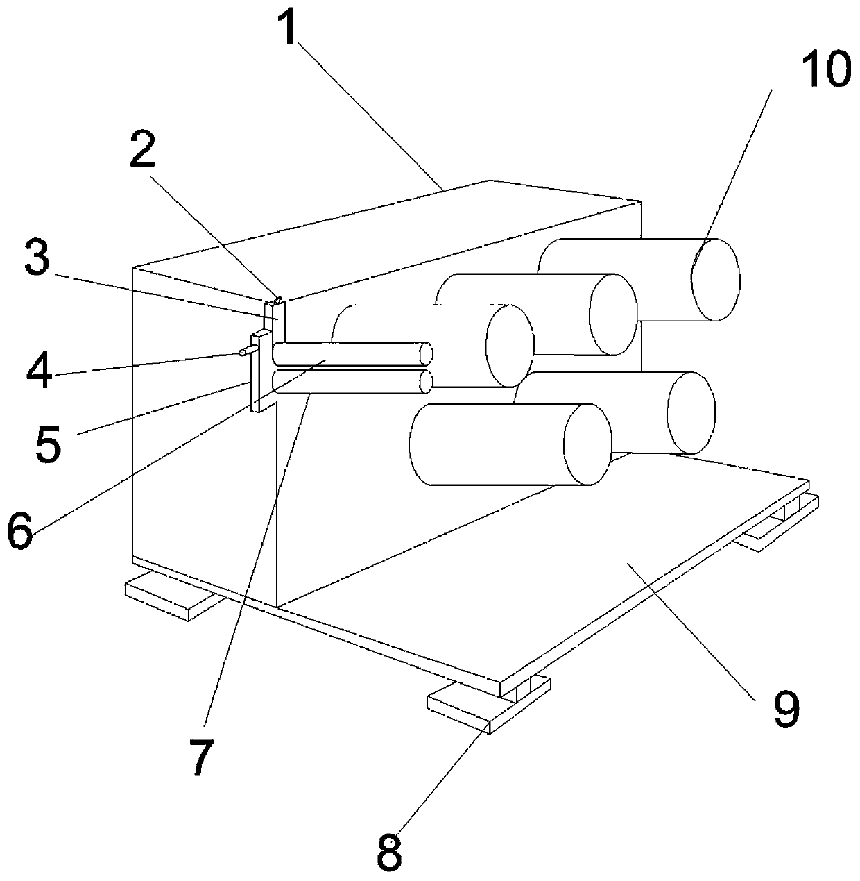
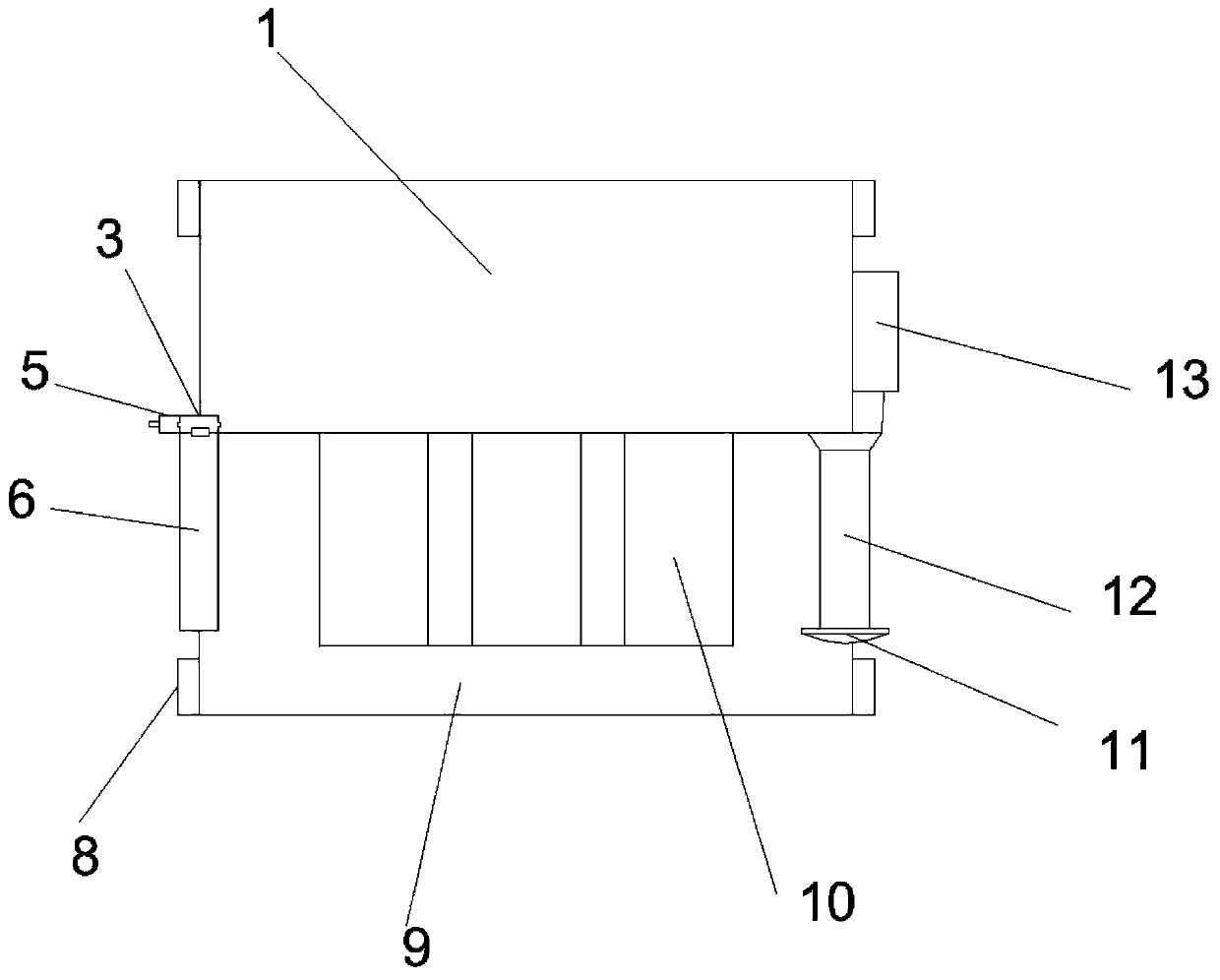
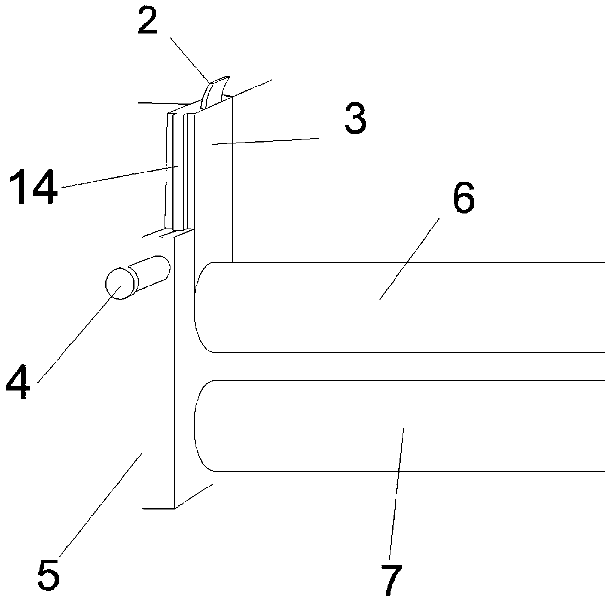

Image

  • Spinning frame drafting device based on textile
  • Spinning frame drafting device based on textile
  • Spinning frame drafting device based on textile

Examples


Embodiment Construction

[0016] The following will clearly and completely describe the technical solutions in the embodiments of the present invention with reference to the accompanying drawings in the embodiments of the present invention. Obviously, the described embodiments are only some, not all, embodiments of the present invention. Based on the embodiments of the present invention, all other embodiments obtained by persons of ordinary skill in the art without making creative efforts belong to the protection scope of the present invention.

[0017] see Figure 1~3 , a textile-based spinning frame drafting device, including a main box 1, a handle 2, a sliding block 3, a fixed pin 4, a fixed plate 5, a sliding stick 6, a fixed stick 7, a shock-absorbing base 8, a receiving plate 9, Winding rod 10, anti-slip knob 11, traction rod 12, traction motor 13 and card slot 14, the main chassis 1, sliding block 3, fixing plate 5, sliding stick 6, fixing stick 7, shock absorbing base 8, receiving plate 9 , wi...


PUM


Abstract

The invention discloses a spinning frame drafting device based on textile, which comprises a main machine case, a handle, a sliding block, a fixing pin, a fixing plate, a sliding rod, a fixing rod, adamping base, a bearing plate, a winding rod, an anti-skid knob, a traction rod, a traction motor and a clamping groove. The sliding block has the advantages that two clamping grooves are fixed on twosides of the sliding block and are fixedly connected with the clamping grooves in the fixing plate in a clamping mode; the fixing pin is of a cylindrical structure and is fixed in a through hole in the fixing plate through sliding connection; the sliding block is also provided with a through hole at a corresponding position; the damping base is internally provided with damping springs; four damping springs are arranged in the damping base; the damping springs are in a bracket structure and are respectively and symmetrically welded and fixed on four corners at the bottom of the bearing plate;the bearing plate is of a plate-shaped structure; one half of the bearing plate is arranged at the bottom of the main machine case; the other half of the bearing plate is arranged below the winding rod; the anti-skid knob is prepared from a metal material and is fixedly connected with the traction rod through a threaded hole.

Description

technical field [0001] The invention relates to a spinning frame drafting device, in particular to a textile-based spinning frame drafting device, and belongs to the technical field of mechanical structures. Background technique [0002] Spinning frame, during the spinning process, the semi-finished roving or sliver is drawn, twisted, and wound into a spinning machine for spun yarn. The combed sliver is combined by the needle carding machine, the structure of the sliver is improved by needle row drafting, and the roving is further twisted on the ring spinning frame to be spun into spun yarn. It is a comprehensive reflection of the pros and cons of each process of the yarn process, and the main function of the drafting device of the spinning frame is: the process of regularly drawing and thinning the fiber aggregates (such as slivers, rovings, etc.), the essence of which is that the fibers are stretched along the aggregate. The relative displacement of the axial direction of...

Claims


Application Information

Patent Timeline
Patent Type & Authority Applications(China)
IPC IPC(8): D01H5/22D01H5/56
Inventor 陈琦咸宁
Owner 江苏世恒织造有限公司
Learn More