Eureka AIR delivers breakthrough ideas for toughest innovation challenges, trusted by R&D personnel around the world.

Energy discharging device, DC power transmission system and energy discharging method

Pending Publication Date: 2019-06-21
TBEA XIAN FLEXIBLE TRANSMISSION & DISTRIBUTIONCO +1
View PDF0 Cites 5 Cited by
  • Summary
  • Abstract
  • Description
  • Claims
  • Application Information

AI Technical Summary

Problems solved by technology

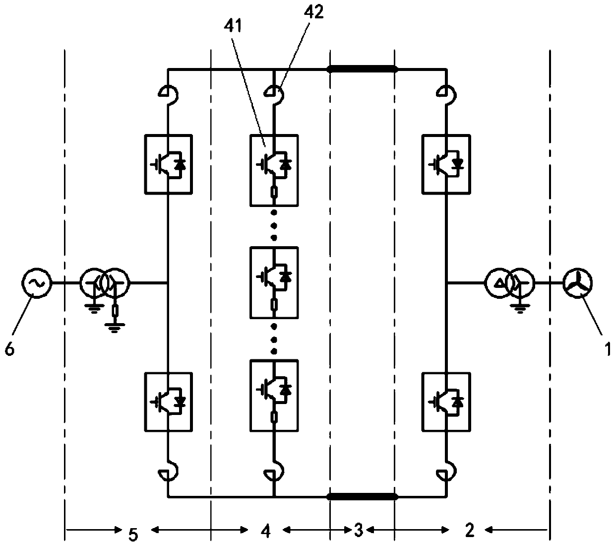
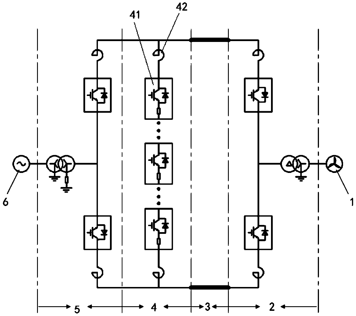
[0004] Offshore wind power transmission system When an AC failure occurs in the onshore station, the voltage of the AC busbar decreases, causing the power transmission of the onshore station to be blocked, resulting in an increase in the voltage of the DC side system. An energy release device is needed to temporarily consume the surplus energy to avoid Transmit onshore faults to offshore grids, causing system downtime and even equipment damage
[0005] The traditional centralized resistance chopper energy discharge device has only two working states: on and off. The voltage difference between these two states is relatively large, so it will cause large du / dt and di / dt during the working process, resulting in Communication abnormality or even equipment damage; unnecessary DC current and DC voltage disturbances are caused under small energy discharge conditions; fluctuations cannot be reasonably suppressed under certain normal operating conditions, such as the third harmonic injection in STATCOM mode ; The energy-discharging resistor in the centralized resistor chopper energy-discharging device is placed outdoors through natural cooling and heat dissipation, and the recovery time is long after the full energy is discharged once, which has potential risks for maintaining high grid availability; in addition, when the system stops After the installation, the centralized resistance chopping discharge energy device cannot discharge the cable smoothly and controllably

Method used


Image

  • Energy discharging device, DC power transmission system and energy discharging method
  • Energy discharging device, DC power transmission system and energy discharging method
  • Energy discharging device, DC power transmission system and energy discharging method

Examples


Embodiment Construction

[0025] The present invention will be described in detail below in conjunction with the accompanying drawings and specific embodiments.

[0026] In the description of the present invention, it should be understood that in the description of the present invention, unless otherwise specified, "plurality" means two or more. In the description of the present invention, it should be noted that unless otherwise specified and limited, the terms "installation", "connection" and "connection" should be understood in a broad sense, for example, it can be a fixed connection or a detachable connection. Connected, or integrally connected; it may be mechanically connected or electrically connected; it may be directly connected or indirectly connected through an intermediary, and it may be the internal communication of two components. Those of ordinary skill in the art can understand the specific meanings of the above terms in the present invention in specific situations.

[0027] refer to f...


PUM


Abstract

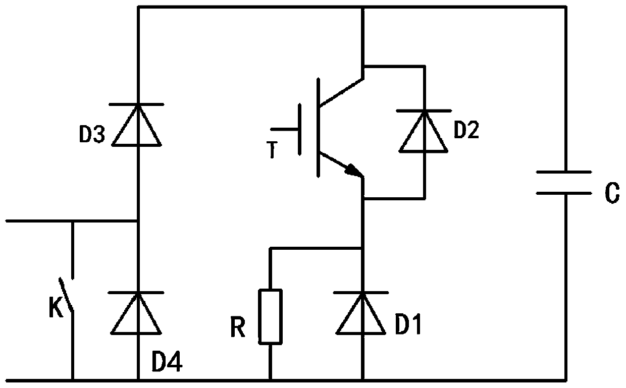
The invention discloses an energy discharging device, a DC power transmission system and an energy discharging method, which are suitable for the field of power transmission of offshore wind power plant. The system comprises an offshore wind power plant, an offshore converter, a DC submarine cable, an energy discharging device, a land converter and an AC main network. Except power grid fault ride-through, DC overcurrent prevention, DC overvoltage prevention and rapid power control, the system also has other properties higher than those of a traditional energy discharging device, large du / dt and di / dt caused by working is eliminated, and energy is smoothly discharged; and meanwhile, a cascaded DC capacitor has a wave smoothing effect, the fluctuation of a DC-side voltage can be reduced under various running modes, and the recovery time after working of the energy discharging device is greatly accelerated.

Description

technical field [0001] The invention belongs to the technical field of power transmission in offshore wind farms, and in particular relates to an energy discharge device, a direct current transmission system and an energy discharge method. Background technique [0002] With the gradual saturation of the development of offshore wind power resources, and the constraints of factors such as hydrology, shipping, fishery, and policies, offshore wind power is developing in the direction of high-power offshore wind power. [0003] Large-capacity, long-distance offshore wind power flexible DC transmission technology has the technical advantages of low line loss, flexible power control, and almost no distance limitation. [0004] Offshore wind power transmission system When an AC failure occurs in the onshore station, the voltage of the AC busbar decreases, causing the power transmission of the onshore station to be blocked, resulting in an increase in the voltage of the DC side syste...

Claims


Application Information

Patent Timeline
Patent Type & Authority Applications(China)
IPC IPC(8): H02J3/38H02M1/32H02H7/22
CPCY02E10/76
Inventor 白鹏田兴刘汉军林卫星
Owner TBEA XIAN FLEXIBLE TRANSMISSION & DISTRIBUTIONCO
Why Eureka
Eureka Blog
Learn More