Transformer capable of cleaning heat-dissipation tube(s) by using ultrasonic waves

A technology for transformers and heat pipes, applied in the field of transformers, can solve the problems of inability to dissipate heat, blockage of pipes, and difficulty in dispersing heat pipes.

Active Publication Date: 2019-06-21
浙江尚能电气股份有限公司
View PDF4 Cites 0 Cited by
  • Summary
  • Abstract
  • Description
  • Claims
  • Application Information

AI Technical Summary

Problems solved by technology

[0003] 1. The pole-mounted transformers are mostly fixed on the utility poles on the rural roads. When the traffic passes by, it is easy to attach dust to the heat dissipation pipes. However, it is impossible to effectively clean the dust in the connection gaps of the heat dissipation pipes during normal rainfall, which makes it easy for the heat dissipation pipes to accumulate heat. At the same time, after the transformer oil has been used for a certain period of time, some impurities will appear in the oil liquid. When the transformer oil flows in the heat dissipation pipe to dissipate heat, the impurities are easily retained in the pipe, thereby blocking the pipe and making it impossible to effectively dissipate heat.
[0004] 2. There are many birds such as sparrows in rural areas, and birds like to stay on the poles, and even build nests on the poles, which will increase the work of maintenance personnel to maintain the transformers on the poles quantity

Method used


Image

  • Transformer capable of cleaning heat-dissipation tube(s) by using ultrasonic waves
  • Transformer capable of cleaning heat-dissipation tube(s) by using ultrasonic waves
  • Transformer capable of cleaning heat-dissipation tube(s) by using ultrasonic waves

Examples


Embodiment Construction

[0031] In order to make the technical means, creative features, goals and effects achieved by the present invention easy to understand, the present invention will be further described below in conjunction with specific embodiments.

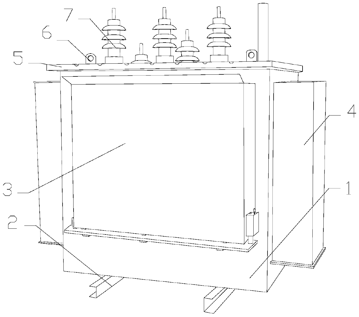
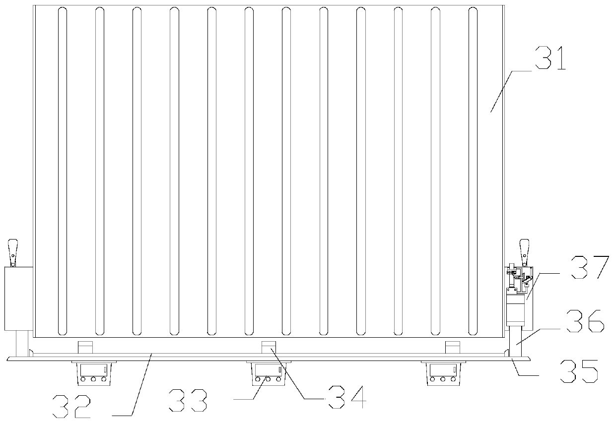
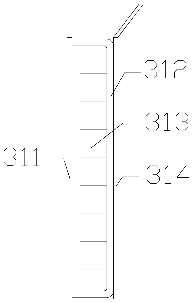
[0032] see Figure 1-Figure 7 , the present invention provides a transformer technical scheme using ultrasonic waves to clean heat dissipation pipes: its structure includes a transformer main body 1, a fixed plate 2, a heat dissipation device 3, an oil storage chamber 4, a top plate 5, a suspension ring 6, and a connector 7, and is characterized in that:

[0033] The front surface of the transformer main body 1 is welded to the back of the heat sink 3, the upper surface of the fixing plate 2 is fixedly mounted on the bottom surface of the transformer main body 1, and the side of the oil storage chamber 4 is welded to the transformer main body 1, so The upper surface of the top plate 5 is provided with a connector 7 , the connector 7 is located on ...


PUM


Abstract

The present invention discloses a transformer capable of cleaning heat-dissipation tube(s) by using ultrasonic waves. The structure of the transformer comprises a transformer main body, fixing plates,a heat-dissipation device, an oil storage room, a top plate, hanging rings and connectors. According to the transformer capable of cleaning the heat-dissipation tube(s) by using the ultrasonic waves,on rainy days, trigger devices start by accumulating a certain amount of rainwater, after the trigger devices at both sides of a heat-dissipater start, a seal plate moves upwardly and blocks the opening on the bottom of the heat-dissipater, and the rainwater begins to accumulate in the heat-dissipater. When a certain water level is reached, the rainwater enters from the small hole(s) on the shell(s) of starting device(s) under the action of water pressure, the rainwater drives floating balls and a connecting rack to float, the conducting rods are conducted with the corresponding contact points, and a ultrasonic transmitter starts. By utilizing the mode of cavitation, the dust in the connection gaps of the heat-dissipation tube(s) is cleaned, and meanwhile sound waves also penetrate the heat-dissipation tube(s) and clean up the impurities in the wall of the heat-dissipation tube(s), so that the effect of cleaning the outer surface(s) and the wall(s) of the heat-dissipation tube(s) is realized, and the heat-dissipation effect is maintained.

Description

technical field [0001] The invention relates to a transformer for cleaning heat-dissipating pipes by ultrasonic waves, which belongs to the field of transformers. Background technique [0002] A transformer is a device that uses the principle of electromagnetic induction to change the voltage of alternating current. There are many types of transformers. Among them, the pole-mounted transformer is a civilian transformer. Compared with other types of transformers, the transformer is small in size and light in weight. , It is often used on fixed poles, hence the name. Unlike other transformers, it needs to build an additional platform and a power distribution room with a large investment, but the pole-mounted transformer can only supply power to a few nearby households, so it is mostly used in rural areas. Existing The traditional technology is not comprehensive and has the following disadvantages: [0003] 1. The pole-mounted transformers are mostly fixed on the utility poles...

Claims


Application Information

Patent Timeline
IPC IPC(8): H01F27/22H01F27/40H01F27/00H01H35/02H01H35/18B08B3/12A01M29/18
Inventor 杨志
Owner 浙江尚能电气股份有限公司
Why Eureka
Try Eureka