Scanning laser radar

A scanning laser and radar technology, applied in the direction of radio wave measurement systems, instruments, etc., can solve problems such as electromagnetic interference, low temperature condensation, scanning dead angle, etc., and achieve the effects of preventing static electricity, reducing interference, and reducing surface resistivity

Active Publication Date: 2019-06-21
SHANDONG FREE OPTICAL TECH CO LTD
View PDF16 Cites 1 Cited by
  • Summary
  • Abstract
  • Description
  • Claims
  • Application Information

AI Technical Summary

Problems solved by technology

[0004] In view of the above analysis, the present invention aims to provide a scanning laser radar, which solves the problem of scanning dead angle, low temperature condensation and electromagnetic interference in the scanning laser radar using the laser scanner scanning method.

Method used


Image

  • Scanning laser radar
  • Scanning laser radar
  • Scanning laser radar

Examples


Embodiment Construction

[0043] Preferred embodiments of the present invention will be specifically described below in conjunction with the accompanying drawings, wherein the accompanying drawings constitute a part of the application and are used together with the embodiments of the invention to explain the principle of the present invention.

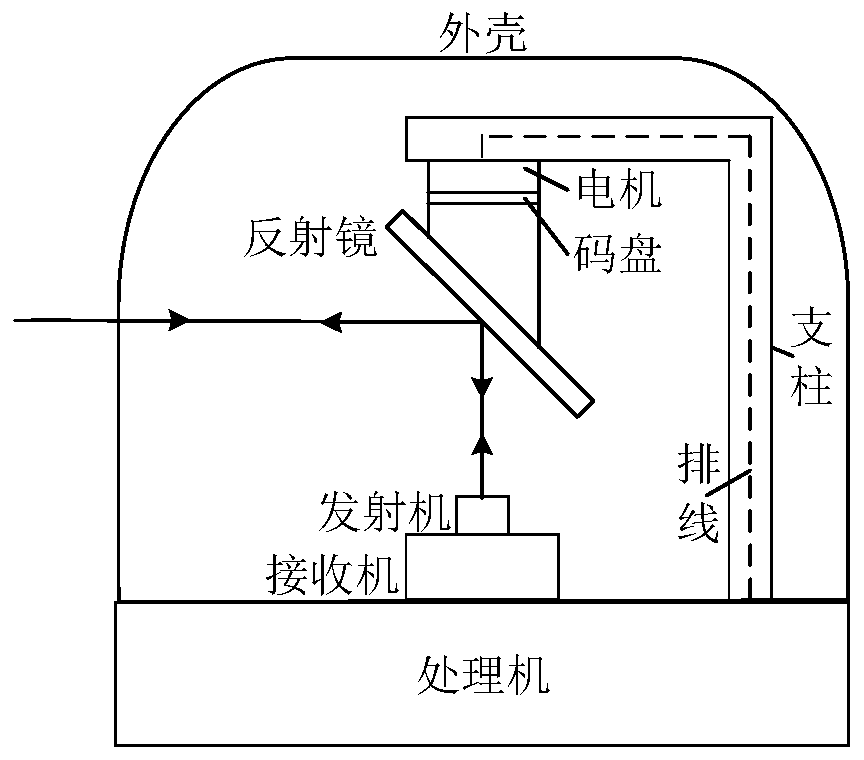
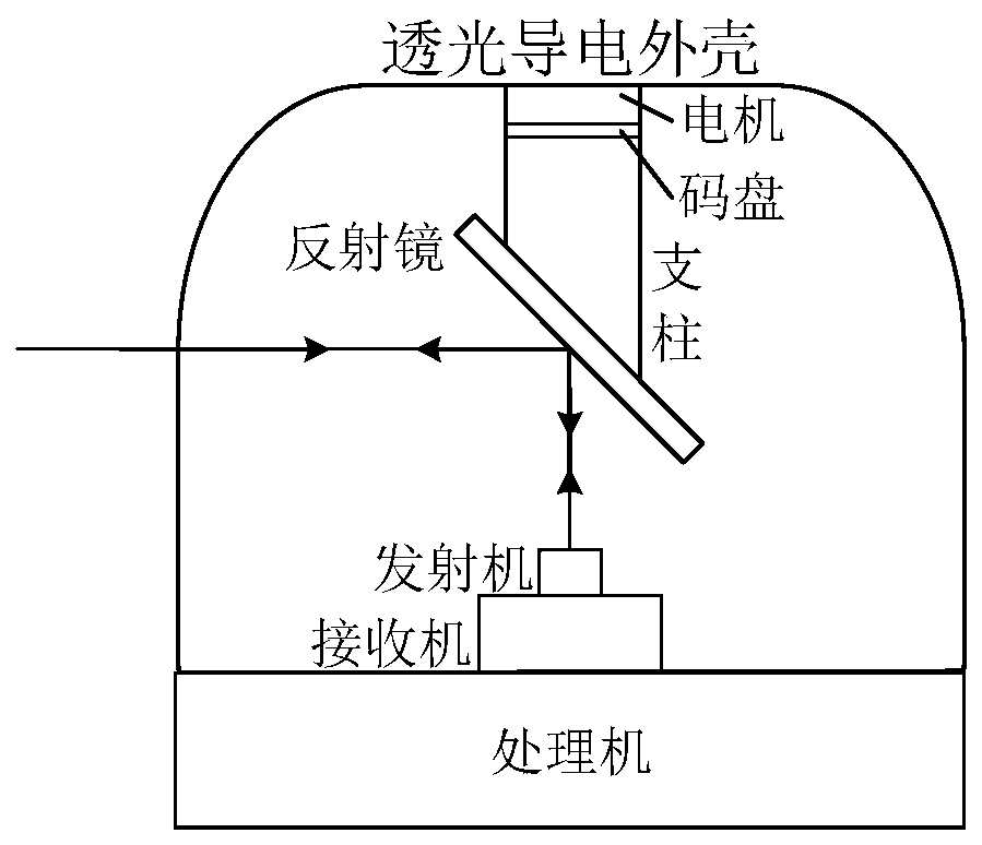
[0044] A specific embodiment of the present invention discloses a scanning laser radar, such as figure 2 As shown, including transmitting and receiving components, processor, laser scanner and light-transmitting conductive housing;

[0045] Transmitting and receiving components include transmitter and receiver;

[0046] The laser scanner includes a rotating mirror, a motor and a code wheel; the rotating mirror includes a pillar and a reflector;

[0047] The motor drives the rotating mirror to rotate, changing the optical path of laser emission and receiving of the lidar to realize the scanning of the field of view; the code disc is used to provide the rotatin...


PUM


Abstract

The invention relates to a scanning laser radar, belongs to the technical field of laser radar, and solves the problems of scanning dead angle, low temperature dew condensation and electromagnetic interference in the scanning laser radar using the laser scanner scanning mode. The laser scanner of the laser radar is fixed on the opposite side of the transmitting and receiving assembly of the laserradar through a 360-degree optical band-pass light-transmitting conductive housing to provide an electrical connection path between the laser scanner and a processor, and the laser scanner realizes 360-degree unoccluded scanning by changing the optical path of the transmitting and receiving assembly of the radar. The low temperature dew condensation is solved by energizing the light-transmitting conductive housing. A light-transmitting shielding layer is arranged on the housing to realize the electromagnetic shielding effect. The problem of scanning dead angle is solved and 360-degree scanningis realized. The interference of other working band light sources to the laser radar is reduced. Besides, the housing dew condensation can be effectively prevented and electromagnetic shielding can be realized, static electricity can be prevented and the impact of electronic dust can be reduced.

Description

technical field [0001] The invention relates to the technical field of laser radar, in particular to a laser radar. Background technique [0002] At present, the scanning lidar that adopts the rotation mode of the transmitter and receiver is powered by an electric slip ring to drive the transmitter and receiver to rotate to achieve 360° field of view scanning, which has the problems of short life and high cost of the electric slip ring. Such as figure 1 As shown in the figure, the scanning laser radar adopts the scanning mode of the laser scanner. The laser scanner is mainly composed of a rotating mirror, a driving motor and a shaft angle encoder. The driving motor drives the rotating mirror to rotate, refracts the laser light path, and realizes the scanning of the field of view. The shaft angle encoder is used to provide the rotation position of the rotating mirror in real time; it is connected between the laser scanner and the radar processor through a bracket, and the po...

Claims


Application Information

Patent Timeline
Patent Type & Authority Applications(China)
IPC IPC(8): G01S7/481G01S7/483G01S7/491
CPCG01S7/491G01S7/483G01S7/481
Inventor 张小富吴振海冯宇翔姚繄蕾张强付晨
Owner SHANDONG FREE OPTICAL TECH CO LTD
Why Eureka
Try Eureka