
Energy-saving and environment-friendly printing and dyeing device

An energy-saving, environmentally friendly and equipped technology, which is applied in the processing of textile material equipment configuration, textile and papermaking, liquid/gas/steam textile processing, etc., can solve the problems of uneven thickness, waste of dyeing resources, uneven distribution of fabric immersion, etc. , to achieve the effect of increasing flow rate and hydraulic pressure, improving uniformity and high efficiency

Active Publication Date: 2019-06-21
陈旭亮
View PDF13 Cites 3 Cited by
  • Summary
  • Abstract
  • Description
  • Claims
  • Application Information

AI Technical Summary

Problems solved by technology

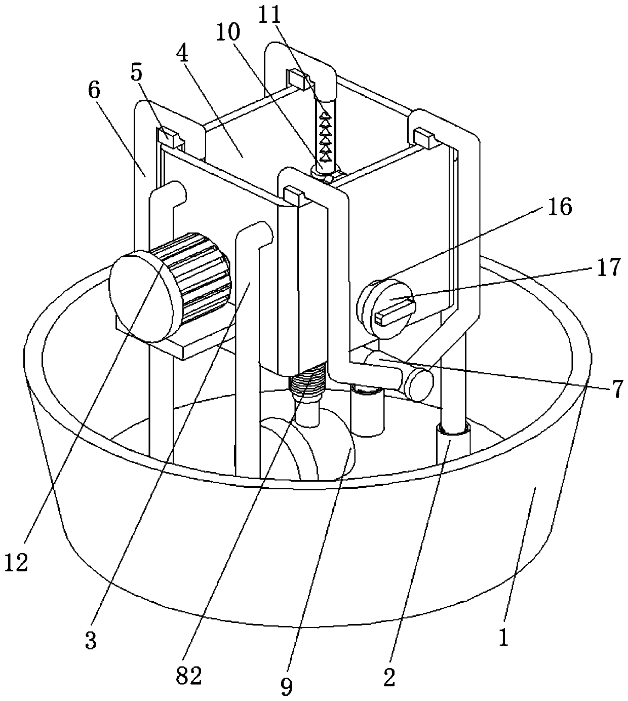
[0004] The invention provides an energy-saving and environment-friendly printing and dyeing equipment, which has the advantages of spray dyeing and then dip-dyeing in the process of lowering the fabric to the dyeing pool, and solves the The thickness of the winding is not uniform, which leads to uneven distribution of the fabric dipping solution in the subsequent dipping process, resulting in rework and unqualified dyeing of the finished fabric. At the same time, it leads to waste of dyeing resources and greatly reduces dyeing. The efficiency of work development and the qualified rate of fabric processing

Method used


Image

  • Energy-saving and environment-friendly printing and dyeing device
  • Energy-saving and environment-friendly printing and dyeing device
  • Energy-saving and environment-friendly printing and dyeing device

Examples


Embodiment Construction

[0026] The technical solutions in the embodiments of the present invention will be clearly and completely described below in conjunction with the accompanying drawings in the embodiments of the present invention. Obviously, the described embodiments are only a part of the embodiments of the present invention, rather than all the embodiments. Based on the embodiments of the present invention, all other embodiments obtained by those of ordinary skill in the art without creative work shall fall within the protection scope of the present invention.

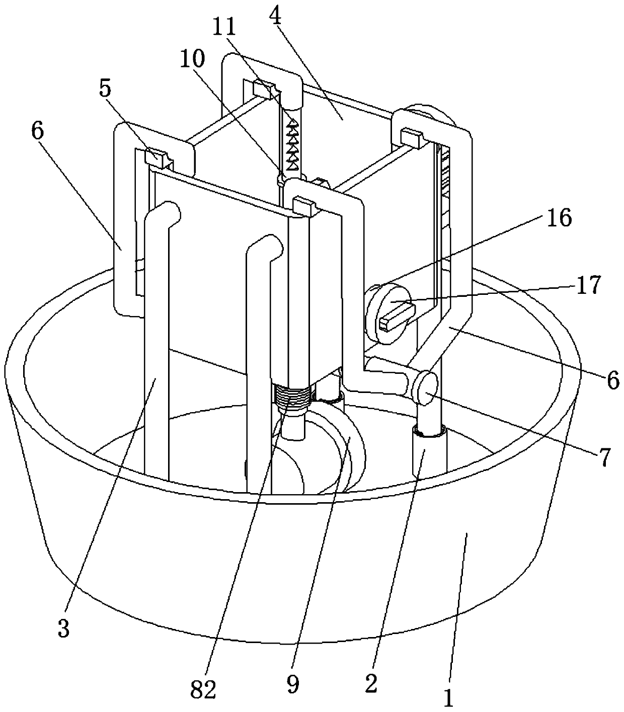
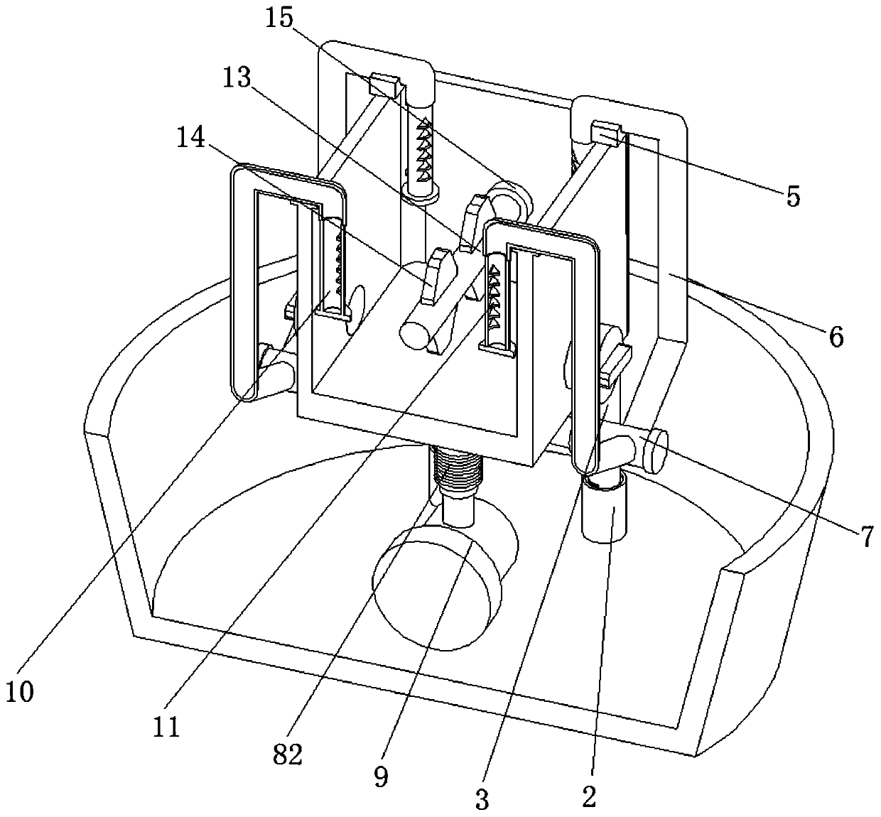
[0027] See Figure 1-5 , An energy-saving and environmentally friendly printing and dyeing equipment, including a dye tank 1. A connecting solenoid 2 is fixedly installed at the bottom of the inner cavity of the dye tank 1. The cavity wall of the connecting solenoid 2 is connected with the outer thread at the bottom end of the supporting screw 3, and the inner side of the supporting screw 3 It is fixedly installed with a stirring drive 1...


PUM


Abstract

The invention relates to the technical field of printing and dyeing equipment, and discloses an energy-saving and environment-friendly printing and dyeing device which comprises a dye tank. Connectingthreaded pipes are fixedly installed at the bottom of an inner cavity of the dye tank, the cavity walls of the connecting threaded pipes are in threaded connection with the exterior of the bottom endof the dye tank, and the ends, away from the connecting threaded pipes, of supporting threaded rods are fixedly connected with the side face of the dye tank. According to the energy-saving and environment-friendly printing and dyeing device, the inner diameter of a transverse guide pipe is three times that of vertical guide pipes, the inner diameter of the vertical guide pipes is 1.5 times that of a guide-out pipe, a driving pump in working makes dye liquor in the inner cavity of the dye tank guided into two distribution side pipes through the guide-out pipe, the dye liquor flowing through the guide-out pipe is distributed through the two distribution side pipes and then is guided out into the vertical guide pipes through the transverse guide pipe, the flow rate and hydraulic pressure ofthe dye liquor are increased under the inner diameter difference of the guide-out pipe, the distribution side pipes and the transverse guide pipe, and thus the uniformity and high efficiency of spraying out the dye liquor through spray holes finally after the dye liquor enters a spray pipe are effectively improved.

Description

Technical field [0001] The invention relates to the technical field of printing and dyeing equipment, in particular to an energy-saving and environment-friendly printing and dyeing equipment. Background technique [0002] Printing and dyeing, also known as dyeing and finishing, is a common fabric processing method, and it is also a general term for pre-treatment, dyeing, printing, finishing, washing, etc. In the dyeing process, the most common dyeing process is dip dyeing and pad dyeing. However, no matter whether the dyeing method is dip dyeing or pad dyeing, the fabric to be dyed needs to be lowered at a uniform speed using a rotating roller and immersed in the dye solution in the dye solution tank, and then the fabric is picked up and subjected to subsequent drying and other treatments. jobs. [0003] The existing invention with publication number CN104611862A discloses a yarn printing and dyeing device. The yarn printing and dyeing device can preliminarily air-dry the yarn aft...

Claims


Application Information

Patent Timeline
IPC IPC(8): D06B1/02D06B3/10D06B23/20
Inventor 陈旭亮
Owner 陈旭亮
Learn More