
Rolling mill for rolling tooth marks on surface of metal belt

A technology of metal strips and tooth marks, applied in metal rolling, metal rolling, metal processing equipment, etc., can solve problems such as failure to meet design requirements, poor stability, poor consistency of tooth marks, etc.

Pending Publication Date: 2019-06-21
贺云坤
View PDF11 Cites 0 Cited by
  • Summary
  • Abstract
  • Description
  • Claims
  • Application Information

AI Technical Summary

Problems solved by technology

[0004] Existing tooth mark pressing machines mostly use the metal belt to pass through the roll gap between the mold roll and the power roll, and the pressure is provided by manually rotating the screw to reduce the roll gap until the mold roll presses the tooth marks on the surface of the metal belt. The raw material is titanium or stainless steel. For metals with high hardness, the pressure provided by the manual rotating screw is too small and the stability is poor, so that the consistency of the rolled tooth marks is poor and cannot meet the design requirements

Method used


Image

  • Rolling mill for rolling tooth marks on surface of metal belt
  • Rolling mill for rolling tooth marks on surface of metal belt
  • Rolling mill for rolling tooth marks on surface of metal belt

Examples


Embodiment Construction

[0028] The technical scheme of the present invention will be further elaborated below in conjunction with accompanying drawing:

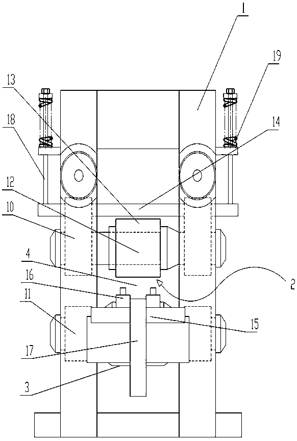
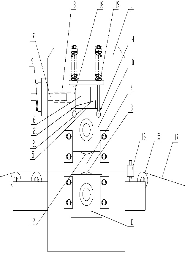
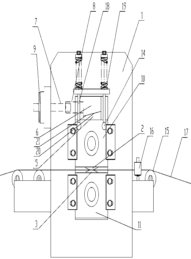
[0029] Such as Figure 1-2 As shown, the rolling mill for rolling tooth marks on the surface of metal strips of the present invention includes: machine body 1; mold roll 2; second roll 3; first inclined block 5; second inclined block 6; rotating part 7; fixed part 8 Dial 9; First bearing seat 10; Second bearing seat 11; Shaft core 12; Die 13; Balance shaft 14; First guide roller 15; Second guide roller 16; The first slope 20; the second slope 21.

[0030] Such as Figure 1-2 As shown, the second bearing seat 11 is fixedly arranged on the machine body 1, there are two second bearing seats 11, the second roller 3 is rotatably arranged on the second bearing seat 11, and the two ends of the second roller 3 are supported on Two second bearing seats 11; the first bearing seat 10 is slidably arranged on the body 1, the first bearing seat 10 is located a...


PUM


Abstract

A rolling mill for rolling tooth marks on the surface of a metal belt comprises a machine body, a second roller rotationally arranged on the machine body, a first bearing block arranged on the machinebody in a sliding manner and a die roller rotationally arranged on the first bearing block and used for installing a die. The axis line of the die roller is parallel to the axis line of the second roller. The sliding direction of the first bearing block is the direction where the axis line of the die roller is close to the axis line of the second roller. A first inclined block is fixedly arrangedon the first bearing block, the machine body is provided with a second inclined block in a sliding manner, the sliding direction of the second inclined block is perpendicular to the sliding directionof the first bearing block, and the contact face of the first inclined block and the second inclined block is an inclined face parallel to the axis line of the die roller. The extension direction ofthe inclined face and the sliding direction of the first bearing block are in intersection and form an acute angle. The inclined face serves as the displacement conduction face, and the roller gap between the die roller and the second roller is accurately controlled.

Description

technical field [0001] The invention relates to a special machine for rolling tooth marks on the surface of a metal strip. Background technique [0002] In the processing of internally threaded pipes and high-efficiency pipes, when the raw material is copper, the ball spinning method is often used for production. When the raw material is titanium or stainless steel and other metals with high hardness, the ball spinning method is inefficient. [0003] In the process of realizing the present invention, the inventor finds that there are at least the following problems in the prior art: [0004] Existing tooth mark pressing machines mostly use the metal belt to pass through the roll gap between the mold roll and the power roll, and the pressure is provided by manually rotating the screw to reduce the roll gap until the mold roll presses the tooth marks on the surface of the metal belt. The raw material is titanium or stainless steel. When other metals with high hardness are use...

Claims


Application Information

Patent Timeline
Patent Type & Authority Applications(China)
IPC IPC(8): B21B1/22B21B15/00
Inventor 贺云坤
Owner 贺云坤
Learn More