Cathode optimization structure of solid oxide fuel cell metal foam runner
A solid oxide and metal foam technology, applied in fuel cells, circuits, electrical components, etc., can solve problems such as increasing ohmic loss, affecting battery temperature distribution and output performance, and large activation overpotential, so as to improve output performance, The effect of short electron transport path and uniform distribution of oxygen concentration
Inactive Publication Date: 2019-06-18
TIANJIN UNIV
View PDF3 Cites 3 Cited by
- Summary
- Abstract
- Description
- Claims
- Application Information
AI Technical Summary
Problems solved by technology
However, a thinner cathode will cause a relatively large activation overpotential at the junction of the ridge and the
Method used
View moreImage
Smart ImageViewing Examples
Examples
 PUM
 Abstract
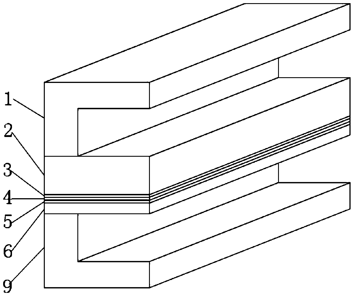
The invention discloses a cathode optimization structure of a solid oxide fuel cell metal foam runner. The structure comprises an anode connector, an anode support layer, an anode catalyst layer, an electrolyte layer, a cathode catalyst layer, a cathode diffusion layer, a metal foam collector, a flat plate metal connector and a cathode connector sequentially combined into a whole from the top down, wherein the metal foam collector is inserted between the cathode diffusion layer and the flat plate metal connector in parallel, to serve as the component of the cathode runner. The cathode catalystlayer and the cathode diffusion layer are made from porous metal ceramic composite material, and the flat plate metal connector is a metal plate with a flat surface and without a groove ridge structure. The porous metal foam collector has good electrical conductivity and thermal conductivity, and relatively good porosity; by using the porous metal foam collector as the solid oxide fuel cell cathode runner, oxygen is easy to be transmitted in the cathode catalyst layer and the cathode diffusion layer, so that the concentration distribution of the oxygen is more uniform, and the condition thatin the traditional groove ridge structure, the oxygen below the ridge is completely consumed is avoided.
Description
technical field [0001] The invention belongs to the field of electrochemical fuel cells, and in particular relates to a structure of a novel cathode channel of a solid oxide fuel cell. Background technique [0002] The current domestic energy consumption structure is irrational, and coal consumption accounts for an excessively large proportion, which is also one of the reasons leading to environmental pollution. Solid oxide fuel cells (SOFC) can use the syngas produced in the coal gasification process as fuel, and further achieve near-zero emissions of pollutants and carbon dioxide through processes such as carbon capture. Therefore, solid oxide fuel cells have attracted much attention in the clean and efficient utilization of coal resources. [0003] At present, solid oxide fuel cells generally use a thinner cathode porous layer to obtain better oxygen transport performance, but for the channel of the trench-ridge structure battery, electrons need to be transferred lateral...
Claims
Login to View More Application Information
Patent Timeline
 IPC IPC(8): H01M8/0232
CPCY02E60/50
Inventor 杜青汪洋詹若冰焦魁
Owner TIANJIN UNIV
Features
- Generate Ideas
- Intellectual Property
- Life Sciences
- Materials
- Tech Scout
- Unparalleled Data Quality
- Higher Quality Content
- 60% Fewer Hallucinations
Learn More Browse by: Latest US Patents, China's latest patents, Technical Efficacy Thesaurus, Application Domain, Technology Topic, Popular Technical Reports.
© 2025 PatSnap. All rights reserved.Legal|Privacy policy|Modern Slavery Act Transparency Statement|Sitemap|About US| Contact US: help@patsnap.com


