
A multi-working-condition design method of a gas-liquid separator for a water-activated battery

A technology of gas-liquid separator and design method, which is applied in the direction of instrumentation, calculation, and electrical digital data processing, etc., which can solve the problems of gas-liquid separator separation efficiency, discharge out of the cabin, and adapt to the small flow range, etc., to achieve good gas-liquid Separation performance, complete gas-liquid separation, and the effect of reducing energy loss

Active Publication Date: 2019-06-14
CHINA ELECTRONIC TECH GRP CORP NO 18 RES INST
View PDF5 Cites 0 Cited by
  • Summary
  • Abstract
  • Description
  • Claims
  • Application Information

AI Technical Summary

Problems solved by technology

[0004] Since the gas-liquid separator for traditional water-activated batteries only considers a single flow rate in the design, when the system flow rate changes, it will have a great impact on the separation efficiency of the gas-liquid separator
If the separation efficiency drops significantly, the electrolyte containing bubbles will enter the pump or the electrolyte will be discharged out of the cabin along with the hydrogen, which will have a negative impact on battery performance
In the applied patent No. CN201521104670 and the patent No. CN201711201534, the structure of the gas-liquid separator has been improved so that it can reduce the pressure loss or achieve reversing, but its structure has a small adaptability to the flow range. The shortcomings of unstable internal air cavity and low separation efficiency require adjustment of the parameters of each component of the gas-liquid separator for optimization

Method used


Image

  • A multi-working-condition design method of a gas-liquid separator for a water-activated battery
  • A multi-working-condition design method of a gas-liquid separator for a water-activated battery
  • A multi-working-condition design method of a gas-liquid separator for a water-activated battery

Examples


Embodiment

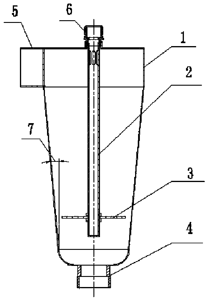
[0087] Among them, the cone angle θ is 6°-10°, the diameter coefficient kd is 0.3-0.5, the low-speed flow coefficient k1 is 1.5-1.7, the high-speed flow coefficient k2 is 2.4-2.65, the length-to-diameter ratio λ is 1.6-1.85, and the value range The effects are similar, in order to better explain the problem, select the value to calculate the corresponding result.

[0088] The design high-speed working condition has a liquid inlet flow rate of 0.0069m 3 / s, the high-speed liquid phase volume fraction is 0.85, and the low-speed working condition feed liquid flow is 0.0056m 3 / s, the volume fraction of the low-speed liquid phase is 0.89, and the density of the transported liquid is 1210kg / m 3 , the gas density is 1.29kg / m 3 , the design high-speed gas phase velocity should not be greater than 5.5m / s.

[0089] (1) According to the design requirements, calculate the main parameters of the gas-liquid separator, and select the diameter coefficient k d is 0.35, the high-speed gas ...


PUM


Abstract

The invention relates to a multi-working-condition design method of a gas-liquid separator for a water-activated battery. The method comprises the steps of determining the main geometric parameters ofthe gas-liquid separator through a corresponding calculation method, wherein the main geometric parameters comprise a liquid inlet diameter D1; the gas outlet diameter D2, the separator base circle diameter D3, the separator barrel length L1 and the like, and meanwhile, matching the installation depth of the flow guide disc and the barrel to adopt a small taper angle form, so that the stability of a gas cavity of the gas-liquid separator can be effectively improved, and the gas-liquid separation is more thorough. The prepared enterprise separator has the good gas-liquid separation performance, the energy loss in the separator can be effectively reduced through experimental verification, the pressure drop is small, and high separation efficiency is achieved under different flow working conditions.

Description

technical field [0001] The invention belongs to the field of gas-liquid separators, in particular to a multi-working-condition design method for a gas-liquid separator for a water-activated battery. Background technique [0002] Hydrogen evolution side reactions often occur in water-activated batteries during discharge. For flow-controlled water-activated batteries, the internal electrolyte circulation is mainly driven by centrifugal pumps after being activated by water ingress. If the electrolyte is not subjected to gas-liquid separation , A large amount of hydrogen gas accumulates in the battery compartment, which will reduce the battery's load capacity, cause battery failure, and even induce battery explosion. Therefore, a gas-liquid separator is required to discharge the generated hydrogen gas out of the battery compartment. [0003] Because water-activated batteries have the advantages of long storage life, high specific energy, and high specific power, they have been u...

Claims


Application Information

Patent Timeline
Patent Type & Authority Applications(China)
IPC IPC(8): G06F17/50
CPCY02E60/50
Inventor 邢树兵闻杰高新龙张新成海超孙凯
Owner CHINA ELECTRONIC TECH GRP CORP NO 18 RES INST
Learn More