
Steam ejector

A technology of ejector and steam, which is applied in jet pumps, machines/engines, non-volume pumps, etc., and can solve the problem of low energy efficiency of steam ejectors

Pending Publication Date: 2019-06-11
HIT HARBIN INST OF TECH KINT TECH
View PDF0 Cites 1 Cited by
  • Summary
  • Abstract
  • Description
  • Claims
  • Application Information

AI Technical Summary

Problems solved by technology

[0014] This adjustment relationship usually cannot meet the actual needs, that is, the steam injector often cannot work in the best state, resulting in relatively low energy efficiency of the steam injector

Method used


Image

  • Steam ejector
  • Steam ejector

Examples


Embodiment Construction

[0027] The present invention will be described in further detail below in conjunction with the drawings and embodiments.

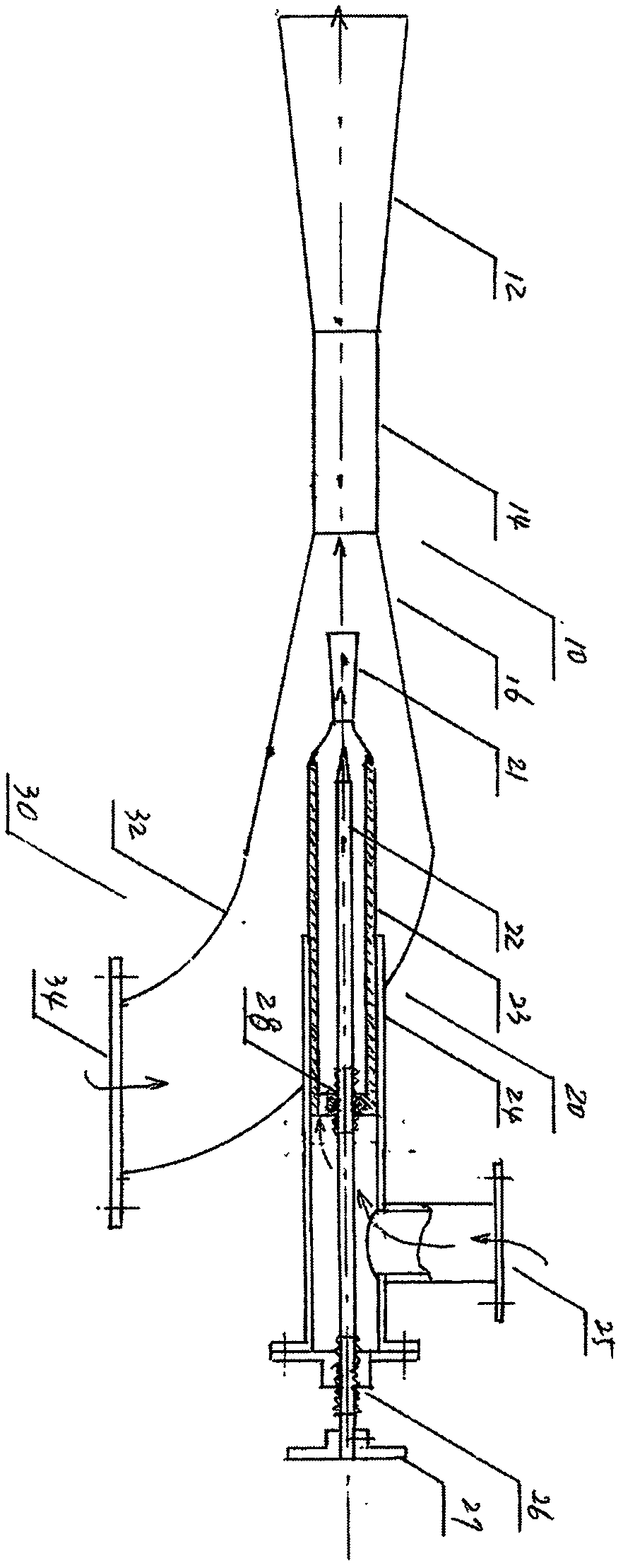
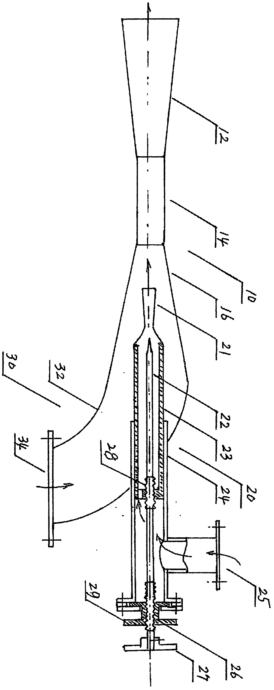
[0028] figure 1 The overall picture of the existing steam ejector is given.

[0029] The existing steam ejector is mainly composed of three parts: a diffuser tube 10, a nozzle 20, and a suction chamber 30.

[0030] The structure of the diffuser tube 10 includes: a divergent outlet section 12, a throat 14 with a constant cross section, and a tapered inlet section 16.

[0031] The structure of the nozzle 20 includes: a nozzle outlet 21, a nozzle steam inlet pipe 23, a nozzle core shaft 22, a sleeve 24, a driving steam inlet 25, an end thread 26, a hand wheel 27, and a steam inlet pipe thread 28.

[0032] The smallest cross section between the nozzle outlet 21 and the nozzle steam inlet pipe 23 is the nozzle throat, and the front end of the nozzle throat is connected to the nozzle inlet. The nozzle mandrel 22 is adjusted by the hand wheel 27 and relies on the end thre...


PUM


Abstract

The invention provides a steam ejector. The steam ejector is composed of three parts of a diffuser pipe, an ejecting nozzle and a suction chamber; the diffuser pipe structurally comprises an exit section expanded gradually, a larynx part with uniform section and an entrance section reduced gradually; the ejecting nozzle structurally comprises an ejecting nozzle outlet, an ejecting nozzle larynx part, an ejecting nozzle steam inlet pipe, an ejecting nozzle spindle, a sleeve, a driving steam inlet, an end thread, a hand wheel and a steam inlet pipe thread; the suction chamber structurally comprises a suction chamber shell and a steam inlet; the outlet of the suction chamber shell is connected with the entrance section of the diffuser pipe, the other end of the entrance section of the diffuser pipe is connected with the larynx part of the diffuser pipe, and the other end of the larynx part is connected with the exit section of the diffuser pipe; one end of the ejecting nozzle spindle is the hand wheel, the other end of the ejecting nozzle spindle is in a circular cone shape, the top end of the circular cone shape points to the ejecting nozzle larynx part located on the end part of thesteam inlet pipe, two sections of threads are located on the ejecting nozzle spindle, the thread close to the hand wheel is matched with the end thread on the sleeve, the thread in the middle is matched with the steam inlet thread, and the steam inlet is slidably attached to the inner wall of the sleeve.

Description

Technical field [0001] The invention relates to thermal engineering technology, in particular to a steam ejector. Background technique [0002] A steam ejector is a device that uses high-pressure steam to suck low-pressure steam to increase the pressure of the low-pressure steam being ejected. [0003] The steam ejector has simple and reliable structure, low operating cost and is widely used, such as vacuum system, refrigeration cycle, chemical industry, rocket and jet aircraft propulsion system, and even the core cooling system of nuclear power plant. [0004] Steam ejectors are widely used in industries that use steam as power, such as textiles, papermaking, petroleum, thermal power, etc., to promote steam circulation and increase low-pressure steam pressure. [0005] Because enterprises in these industries produce low-pressure steam during the production process, there may be multiple levels of steam in a production plant or workshop. Steam ejectors can use the available energy of ...

Claims


Application Information

Patent Timeline
Patent Type & Authority Applications(China)
IPC IPC(8): F04F5/18F04F5/36
Inventor 李金峰李伟尚德敏
Owner HIT HARBIN INST OF TECH KINT TECH
Learn More