Charging device used during driving of electric trolley
A technology of electric car and charging device, which is applied in the direction of electric car charging technology, battery circuit device, electric car, etc., can solve the problems of inconvenient charging of electric car charging stations, affecting the use of electric cars, etc., so as to improve the flexibility of selection, Reduced weight and easy cleaning
- Summary
- Abstract
- Description
- Claims
- Application Information
AI Technical Summary
Problems solved by technology
Method used
Image


Examples
Embodiment 1
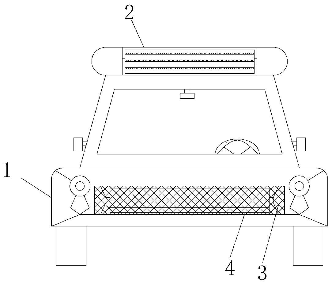
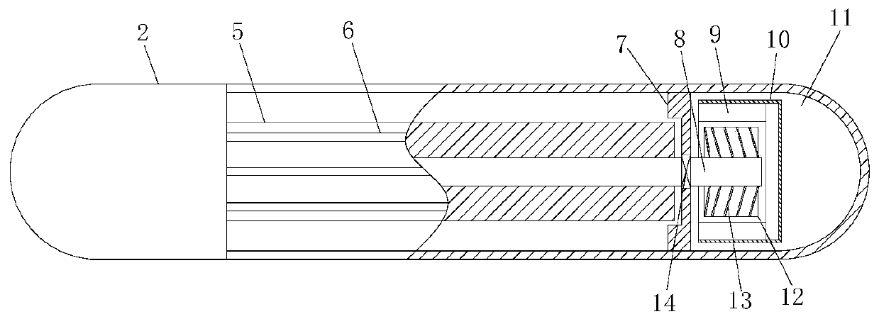
[0033] see Figure 1-4 , a kind of charging device used when the electric trolley is running, comprising the electric trolley body 1, the front of the car body of the electric trolley body 1 is provided with a front screen 3, and the electric trolley body 1 behind the front screen 3 is equipped with a front A generator 4, a generator 2 is installed at the top position of the electric trolley body 1, and a generator area 11 is respectively arranged on the left and right sides of the generator 2, and the generator area 11 on the left and right sides in the generator 2 is installed There is a drum 5, and a partition 7 is arranged between the drum 5 and the power generation area 11. The drum 5 is evenly equipped with air strip grooves 6, and the air strip grooves 6 are positive blades 17 designed perpendicular to the drum 5;
[0034] A rotating shaft 8 is installed in the drum 5, and the two ends of the rotating shaft 8 are fixed on the partition plate 7 through bearings 14 respec...
Embodiment 2
[0036] see Figure 1-3 , 5, a kind of charging device that is used when the electric trolley travels, comprises electric trolley body 1, and the car body front of described electric trolley body 1 is provided with front screen 3, and the electric trolley body 1 behind front screen 3 installs There is a front generating tube 4, and a generating tube 2 is installed on the top position of the electric trolley body 1. The left and right sides of the generating tube 2 are respectively provided with power generating areas 11, and the power generating areas 11 on the left and right sides in the generating tube 2 A drum 5 is installed between the drum 5 and a partition 7 is arranged between the drum 5 and the power generation area 11. The drum 5 is evenly equipped with a wind strip groove 6, and the wind strip groove 6 is an inclined blade 18 with a certain inclination angle;
[0037] A rotating shaft 8 is installed in the drum 5, and the two ends of the rotating shaft 8 are respectiv...
Embodiment 3
[0039] see Figure 1-3 , 6, a kind of charging device that is used when the electric trolley travels, comprises electric trolley body 1, and the car body front of described electric trolley body 1 is provided with front screen 3, and the electric trolley body 1 behind front screen 3 installs There is a front generating tube 4, and a generating tube 2 is installed on the top position of the electric trolley body 1. The left and right sides of the generating tube 2 are respectively provided with power generating areas 11, and the power generating areas 11 on the left and right sides in the generating tube 2 A drum 5 is installed between the drum 5 and a partition 7 is arranged between the drum 5 and the power generation area 11. The drum 5 is evenly equipped with a wind strip groove 6, and the wind strip groove 6 is a groove 19, and the groove 19 and the drum 5 form a dovetail. type structure;
[0040]A rotating shaft 8 is installed in the drum 5, and the two ends of the rotati...
PUM
 Abstract
Description
Claims
Application Information
 - R&D
- Intellectual Property
- Life Sciences
- Materials
- Tech Scout
- Unparalleled Data Quality
- Higher Quality Content
- 60% Fewer Hallucinations
Browse by: Latest US Patents, China's latest patents, Technical Efficacy Thesaurus, Application Domain, Technology Topic, Popular Technical Reports.
© 2025 PatSnap. All rights reserved.Legal|Privacy policy|Modern Slavery Act Transparency Statement|Sitemap|About US| Contact US: help@patsnap.com