
Dust-free wall grooving machine

A slotting machine and wall technology, which is applied to work accessories, manufacturing tools, stone processing equipment, etc., can solve the problems of little help in improving efficiency, high labor costs, and high labor intensity, so as to reduce the internal working temperature environment and save Manpower effort, the effect of improving cleanliness

Inactive Publication Date: 2019-06-11
闫宇
View PDF0 Cites 6 Cited by
  • Summary
  • Abstract
  • Description
  • Claims
  • Application Information

AI Technical Summary

Problems solved by technology

[0002] At present, the general method for wall pipe laying and grooving in building electrical installation and construction is: use a portable cutting machine to cut out two groove lines, and then use a special electric hammer to chisel. This method has two major disadvantages. One is too large. Dirty, flying dust makes the elderly prone to terrible severe lung disease, which leads to higher wages. The other is high labor intensity and low efficiency. Everyone who has tried it has denied its use value. There is a double Chip cutting machine, its biggest disadvantage is: it is damaged, the cost is high, and it is not helpful to improve the efficiency. At the same time, the dust generated during the slotting process cannot be discharged in time, so that the market share of the equipment is not high.

Method used


Image

  • Dust-free wall grooving machine
  • Dust-free wall grooving machine

Examples


Embodiment Construction

[0014] The following will clearly and completely describe the technical solutions in the embodiments of the present invention with reference to the accompanying drawings in the embodiments of the present invention. Obviously, the described embodiments are only some, not all, embodiments of the present invention.

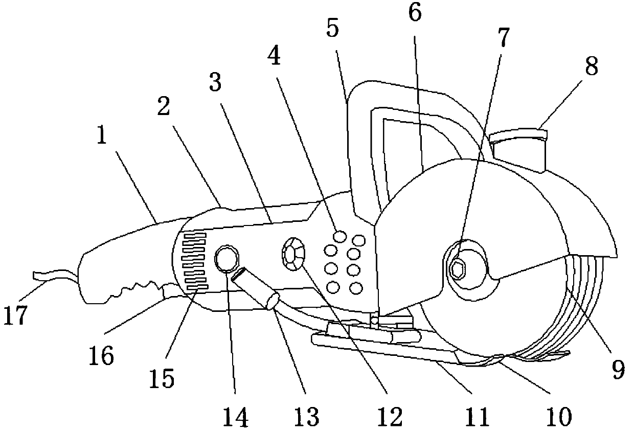
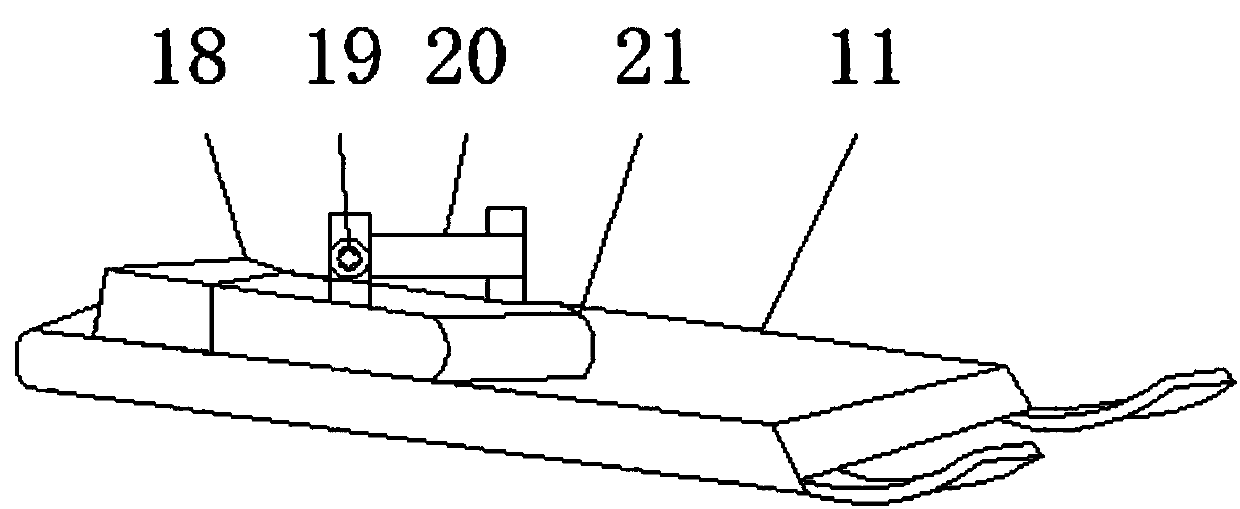
[0015] refer to Figure 1-2 , a dust-free wall slotting machine, comprising a main box 2, a control panel 3, a protective case 6 and a fixed plate 11, a control handle 1 is installed on the left side of the main box 2, and a start button 16 is installed on the lower side of the control handle 1, A power cord 17 is installed on the left side of the main box 2, a control panel 3 is installed on the front surface of the main box 2, and a fuel tank port 14 is installed on the surface of the control panel 3, and a speed knob 12 is installed on the surface of the control panel 3, and the right side of the speed knob 12 is installed Ventilation holes 4 are arranged, and the...


PUM


Abstract

The invention discloses a dust-free wall grooving machine. The machine comprises a main machine box, a control panel, a protective shell and a fixing plate, wherein a control handle is arranged on theleft side of the main machine box, a starting button is arranged on the lower side of the control handle, a power line is installed on the left side of the main machine box, a control panel is installed on the front surface of the main machine box, an oil tank opening is formed in the surface of the control panel, a lifting handle is arranged on the upper side of the main machine box, a protective shell is arranged on the right side of the main machine box, the lower side of the protective shell is provided with a fastening screw ring, the lower side of the main machine box is provided with the fixing plate, the right side of the fixing plate is provided with a baffle plate, the upper side of the fixing plate is provided with a supporting rod, the surface of the supporting rod is providedwith a screw, the upper side of the fixing plate is provided with a hydraulic device, and the hydraulic device is connected with the oil tank opening through an oil supply pipe. According to the machine, a dust removal pipe arranged on the upper side of the protective shell can be connected with an air draft device to clean dust generated in the grooving process, and cleanliness of a working environment of the machine is improved.

Description

technical field [0001] The invention relates to the technical field of slotting, in particular to a dust-free wall slotting machine. Background technique [0002] At present, the general method for wall pipe laying and grooving in building electrical installation and construction is: use a portable cutting machine to cut out two groove lines, and then use a special electric hammer to chisel. This method has two major disadvantages. One is too large. Dirty, flying dust makes the elderly prone to terrible severe lung disease, which leads to higher wages. The other is high labor intensity and low efficiency. Everyone who has tried it has denied its use value. There is a double The biggest disadvantages of chip grooving machine are: damage, high cost, and little help to improve efficiency. At the same time, the dust generated during the grooving process cannot be discharged in time, which makes the market share of the equipment not high. Contents of the invention [0003] The...

Claims


Application Information

Patent Timeline
IPC IPC(8): B28D1/24B28D7/00B28D7/02
Inventor 闫宇
Owner 闫宇
Learn More