Portable vision tester

A tester and portable technology, applied in the field of vision testing equipment, can solve the problems of inaccurate vision, weak sense of direction, deviation and other problems of vision testers, and achieve accurate test results, easy to carry, and reduce stress.

Active Publication Date: 2019-06-11
HENAN NORMAL UNIV
View PDF7 Cites 1 Cited by
  • Summary
  • Abstract
  • Description
  • Claims
  • Application Information

AI Technical Summary

Problems solved by technology

[0002] Nowadays, when testing eyesight, the eye chart is hung on the wall. The vision tester stands at a distance of about 5 meters from the vision chart, covers one eye, distinguishes the direction of the word E in the eye chart, and then obtains the specific vision of the vision tester. However, in the actual test, the distance of 5 meters will be more or less biased, coupled with the influence of ambient light at different times, the vision tester's vision is not accurate, and the vision chart is not convenient to carry and requires a flat wall For many people, the process of simultaneous testing is rather boring. Many people often perform vision tests at the same time, and doctors do not have the patience to carefully confirm the vision of the testers. When performing vision tests, people focus on seeing In the direction of clear letters, there may be situations where the direction the fingers point is inconsistent with the direction they see. Some people are not born with a strong sense of direction, and may point to the wrong direction, resulting in inaccurate test results. If the interest test does not cooperate with the doctor's detection, it is more likely to lead to inaccurate vision test results, so it is necessary to design a portable vision tester

Method used


Image

  • Portable vision tester
  • Portable vision tester
  • Portable vision tester

Examples


Embodiment Construction

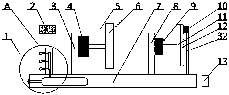
[0021] The present invention is specifically described below in conjunction with accompanying drawing, as Figure 1-7 As shown, a portable vision tester includes a device body 1, a base 7 is provided at the bottom of the device body 1, and an air intake valve 14 is provided at the left end of the base 7, and the air intake valve 14 is connected with the gas tank 15 in the base 7 through a pipeline. 7. A fixed plate 18 is arranged on the left side of the upper side. The left side of the fixed plate 18 is provided with a decompression ball 16. The decompression ball 16 is arranged on the fixed plate 18 through a fixed rod. Set the gas distribution valve 17, the decompression ball 16 is connected with the gas distribution valve 17 through the pipeline, the lower side of the gas distribution valve 17 is connected with the gas tank 15 through the pipeline, and the silicone layer 31 is arranged on the outside of the decompression ball 16, and the silicone layer 31 is a bionic human b...


PUM


Abstract

The invention discloses a portable vision tester. The portable vision tester comprises an eye lens, a lens disc, a letter disc, a decompression ball and a whistle. The portable vision tester is openedby medical staff, the lens in the lens disc is aligned with a lens barrel through a first motor box; an electric lamp is turned on, and a vision tester observes the letter orientation on the letter disc through the lens; when a vision tester clearly sees the orientation of the letter clearly; the pressure reducing ball which is correspondingly placed upwards is pressed; air in the air bag on thepressure reducing ball is extruded out; extruded air makes the whistle in the decompression ball make a sound. According to the existing vision testing, a visual chart generally is hung on a wall, anddirections of Es in a visual chart are distinguished; however, according to the detection method, an eyesight tester (especially primary and secondary school students) can feel pressure, the test process is interesting, and meanwhile, the light environment can influence the detection result, so that the measured eyesight is inaccurate. The portable vision tester enables the test result to be moreaccurate, is more convenient for medical staff to carry, and enables the detection result to be more accurate.

Description

technical field [0001] The invention relates to vision testing equipment, in particular to a portable vision testing instrument. Background technique [0002] Nowadays, when testing eyesight, the eye chart is hung on the wall. The vision tester stands at a distance of about 5 meters from the vision chart, covers one eye, distinguishes the direction of the word E in the eye chart, and then obtains the specific vision of the vision tester. However, in the actual test, the distance of 5 meters will be more or less biased, coupled with the influence of ambient light at different times, the vision tester's vision is not accurate, and the vision chart is not convenient to carry and requires a flat wall For many people, the process of simultaneous testing is rather boring. Many people often perform vision tests at the same time, and doctors do not have the patience to carefully confirm the vision of the testers. When performing vision tests, people focus on seeing In the direction...

Claims


Application Information

Patent Timeline
Patent Type & Authority Applications(China)
IPC IPC(8): A61B3/032A61M21/02
Inventor 王科李梦梦陈炳全董星池马钦龙
Owner HENAN NORMAL UNIV
Why Eureka
Try Eureka