Electric valve and water leakage protection device
A technology of electric valves and electric actuators, which is applied in the direction of valve devices, valve operation/release devices, valve details, etc., and can solve the problems of low accuracy in water pipe micro-leakage judgment
- Summary
- Abstract
- Description
- Claims
- Application Information
AI Technical Summary
Problems solved by technology
Method used
Image
Examples
Embodiment 1
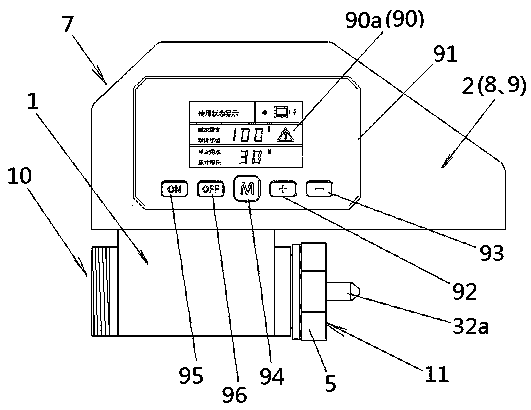
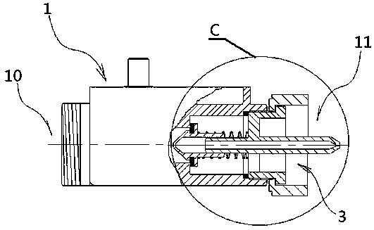
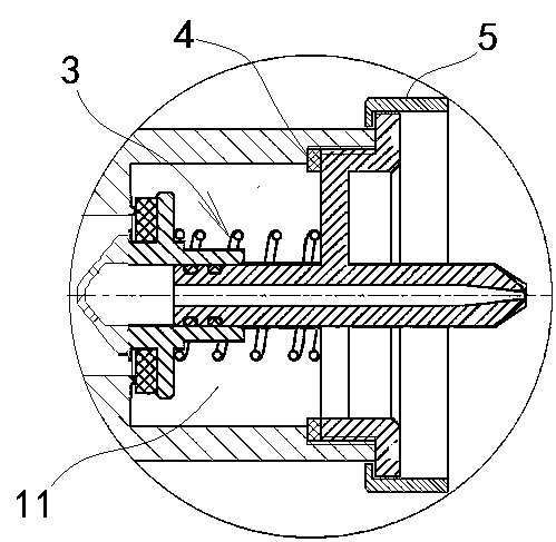
[0044] Such as figure 1 , figure 2 , image 3 , Figure 4 , Figure 5 , Figure 6 , Figure 7 , Figure 8 , Figure 9 and Figure 10 shown
[0045] An electric valve, including an electric valve body 7, the electric valve body 7 is composed of a first valve body 1 and an electric actuator 2 arranged on the first valve body 1, in this embodiment, the first valve body 1 is a ball valve and an electric actuator 2 is arranged on the first valve body 1 , and the two are combined to form an electric ball valve. The first valve body 1 is provided with a first water inlet 10 and a first water outlet 11 .
[0046] The electric actuator 2 includes a power actuator 8 and an electronic controller 9. The electronic controller 9 includes an internal microelectronic control module 90 and a control panel 91 arranged on its outer surface. The microelectronic control module 90 is connected to the control panel 91 And the rated control parameters of the microelectronic control module ...
Embodiment 2
[0054] In this embodiment, the microelectronic control module 90 also includes an alarm circuit ( Figure 18 shown) or / wireless transmission control line ( Figure 19 shown), others are the same as in Embodiment 1, and will not be repeated here.
Embodiment 3
[0056] Such as Figure 20 , Figure 21 , Figure 22 , Figure 23 and Figure 24 As shown, a water leakage protection device includes a water flow sensor 6 and the electric valve body 7 described in Embodiment 1. The water flow sensor 6 is an impeller type water flow sensor, mainly composed of a second valve body 60 and a The water flow rotor assembly 61 in the inner cavity of the second valve body 60 and the Hall sensor 62 arranged outside the second valve body 60, the Hall sensor 62 is connected to the electronic controller 9, and converts the dynamic change of the water flow into a pulse signal After being fed back to the electronic controller 9 and received by its internal microelectronic control module 90, at least two design functions are achieved: the setting and Control, once the upper limit of one of the set rated parameters is touched, it is considered that the water is abnormal, and the water flow control signal is immediately generated and output to the power ac...
PUM
 Abstract
Description
Claims
Application Information
 - Generate Ideas
- Intellectual Property
- Life Sciences
- Materials
- Tech Scout
- Unparalleled Data Quality
- Higher Quality Content
- 60% Fewer Hallucinations
Browse by: Latest US Patents, China's latest patents, Technical Efficacy Thesaurus, Application Domain, Technology Topic, Popular Technical Reports.
© 2025 PatSnap. All rights reserved.Legal|Privacy policy|Modern Slavery Act Transparency Statement|Sitemap|About US| Contact US: help@patsnap.com


