
A traction system for clamping glass by short rollers and its application method

A traction system and short roller technology, which is applied to the traction system field of short rollers clamping glass, can solve the problems of glass cracking, insufficient clamping force, large limitations, etc., and achieve the effect of saving cost and improving production efficiency.

Active Publication Date: 2021-10-12
IRICO DISPLAY DEVICES
View PDF6 Cites 0 Cited by
  • Summary
  • Abstract
  • Description
  • Claims
  • Application Information

AI Technical Summary

Problems solved by technology

When fewer rollers are used to clamp and pull the glass, the clamping force of the rollers on the glass is relatively large. If the clamping force is too large, the coating layer of the rollers will wear quickly and the glass may be clamped due to excessive clamping force. If the clamping force is reduced, the clamping force will be insufficient. In this case, the gravity of the hanging glass will be greater than the frictional force, and the glass and the roller coating will slip. The short roller clamping traction system of the driving device has great limitations in the control of the glass clamping force, and the operation is difficult
[0004] Based on the above reasons, it is necessary to adopt new clamping and traction measures for the production of large-size glass plates, so as to overcome the adverse effects of the above problems on glass production.

Method used


Image

  • A traction system for clamping glass by short rollers and its application method
  • A traction system for clamping glass by short rollers and its application method
  • A traction system for clamping glass by short rollers and its application method

Examples


Embodiment Construction

[0035] The present invention will be further described in detail below in conjunction with specific embodiments, which are explanations of the present invention rather than limitations.

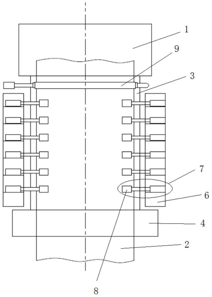
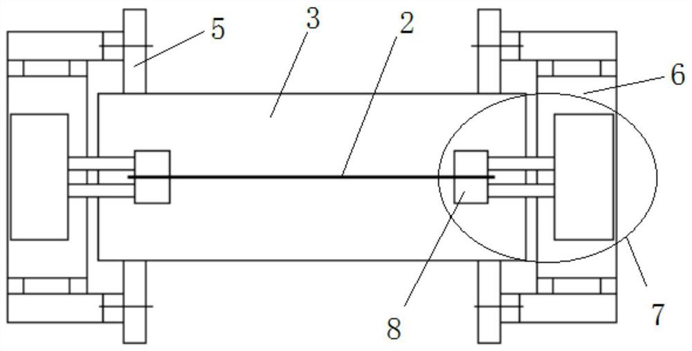
[0036] see figure 1 and figure 2 , the traction system of the present invention for clamping glass by short rollers is located between the overflow device 1 and the cutting device 4, and includes a support arm 5, a bracket 6 and a short roller mechanism 7;

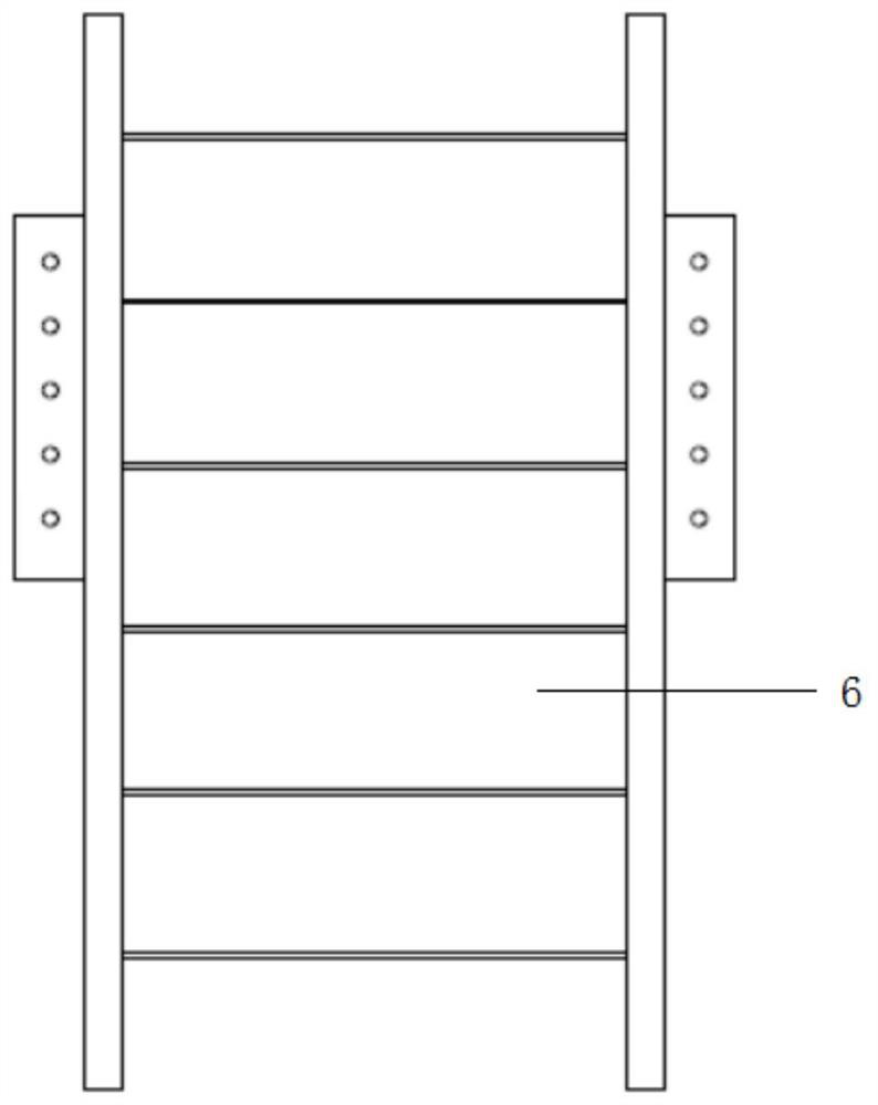
[0037] Two support arms 5 are respectively arranged at the middle height of both sides of the annealing furnace 3. The support arms 5 are used to support the annealing furnace 3 and are distributed at the four corners of the annealing furnace 3. There are two supports 6, which are symmetrically fixed on both sides of the annealing furnace 3 respectively. On the support arm 5, the structure of the bracket 6 is as follows image 3 and Figure 4 As shown, no less than three platforms are fixedly arranged on the support 6, and the platfor...


PUM


Abstract

The present invention is a traction system and using method for clamping glass by short rollers. The traction system includes two supports and an even number of short roller mechanisms; the supports are fixed on both sides of the annealing furnace, and no less than three platforms are arranged on the supports, each platform A short roller mechanism is fixed on the top, and the short roller mechanism includes two short rollers. The power device in the short roller mechanism is used to drive the short rollers to clamp and pull the glass; the method of use includes step 1, using the through roller to clamp and pull the glass, so that the glass No shaking; step 2, run the short roller mechanism one by one from top to bottom, the power device in each short roller mechanism drives two short rollers to clamp the glass; step 3, after all the short rollers of the short roller mechanism clamp the glass The through rollers are opened, and the glass is clamped and pulled by all the short rollers. Avoid the disadvantages of cracking of the glass due to the large clamping force due to the small number of clamping glass rollers, and the rapid wear of the roller covering layer, and reduce the adverse effects of the vibration generated by the cutting equipment on the glass quality when cutting and breaking the glass .

Description

technical field [0001] The invention belongs to the field of flat glass manufacturing, and in particular relates to a traction system for clamping glass by short rollers and a using method. Background technique [0002] The overflow down-draw method is one of the main methods of manufacturing flat glass. In the overflow down-draw method, the molten glass flows down from the overflow tank, and the edge of the glass ribbon is cooled and shaped by the edge roller to form a certain width of glass. To form glass of ideal thickness, edge rollers and rollers use the difference in line speed to pull the glass into the required thickness with rollers. [0003] Long rolls are usually used in the production of small-sized glass plates. As the size of glass plates increases, the glass pulling equipment gradually changes from long rolls to short rolls. In the prior art, one or two sets of short rollers with driving devices are usually used to clamp and pull the glass, and the glass afte...

Claims


Application Information

Patent Timeline
Patent Type & Authority Patents(China)
IPC IPC(8): C03B17/06
Inventor 李淼晁耀定王答成
Owner IRICO DISPLAY DEVICES
Learn More