


Quick Research
Generate reliable direction feasibility study reports for your R&D in just a few steps.

Technical Q&A
Discover and master advanced knowledge NOW. Basics, ideas, possibilities, all at once.

Find Solutions
As an expert in R&D theories, this can generate solutions to your technical problems instantly.

Evaluate Feasibility
Analyze your overall solution with one click, know your potential R&D risks in advance.

Monitor Landscape
Get weekly tech updates, stay abreast of the latest tech innovations and key insights.
Glass cup turnover device for glass cup production line
A technology of turning device and glass cup, which is applied in the directions of transportation and packaging, conveyor objects, etc., can solve the problems of low turning efficiency and high working intensity of human body, etc.
- Summary
- Abstract
- Description
- Claims
- Application Information
AI Technical Summary
Problems solved by technology
Method used
Image


Examples
Embodiment 1
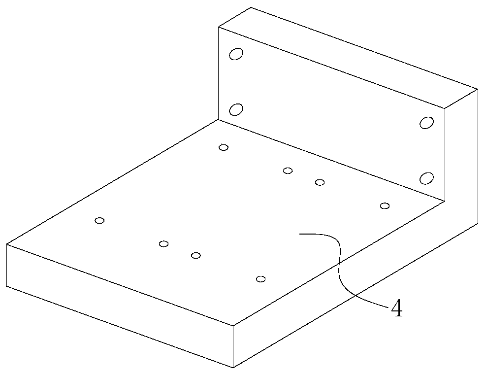
[0024] The glass cup production line uses a glass cup turning device. When the glass cup moves on the production line, it moves to the front of the annealing furnace. The rotating cylinder 1 drives the turning rod 3 to rotate clockwise 180° through the connecting sleeve 2, so that the supporting plate 4 and the The rotating cylinder two 5 and the rotating cylinder three 6 connected to the supporting plate 4 also rotate 180° along with the turning rod 3, and then the rotating cylinder two 5 and the rotating cylinder three 6 work simultaneously, and the rotating shaft of the rotating cylinder two 5 and the rotating cylinder three 6 The rotating shaft drives the frame rod 9 to clamp the glass cup with the mouth upwards in the middle through the parallelogram mechanism formed by the first connecting rod 7, the second connecting rod 8, the hinge seat 40, the first cylindrical hole 90 and the second cylindrical hole 91, and then rotates Cylinder one 1 drives the turning lever 3 to ro...
Embodiment 2
[0026] On the basis of Example 1, the flipping bar 3 is an "L"-shaped structure, which facilitates the installation of two automatic conveying lines; the supporting plate 4 is an "L"-shaped plate structure, which facilitates the installation of a flipping bar 3 The installation of the rotary cylinder two 5 and the rotary cylinder three 6 is convenient; the frame bar 9 is a "T" structure, which realizes the connecting rod one 7, the connecting rod two 8, the hinge seat 40, the cylindrical hole one 90 and the The second cylindrical hole 91 forms a parallelogram mechanism, which is stable in clamping; the inside of the frame rod 9 is provided with a rubber pad 92 to avoid scratches on the surface of the glass bottle.
PUM
 Abstract
Description
Claims
Application Information
 - R&D Engineer
- R&D Manager
- IP Professional
- Industry Leading Data Capabilities
- Powerful AI technology
- Patent DNA Extraction
Browse by: Latest US Patents, China's latest patents, Technical Efficacy Thesaurus, Application Domain, Technology Topic, Popular Technical Reports.
© 2024 PatSnap. All rights reserved.Legal|Privacy policy|Modern Slavery Act Transparency Statement|Sitemap|About US| Contact US: help@patsnap.com