
Thermal management system used for electric automobile

A thermal management system and electric vehicle technology, applied in the field of electric vehicles, can solve the problems of reducing the mileage of electric vehicles, battery power loss, insufficient heating capacity of heat pumps, etc., to achieve the effect of improving low-temperature heating capacity and saving energy

Active Publication Date: 2019-06-07
GUANGZHOU INST OF ENERGY CONVERSION - CHINESE ACAD OF SCI
View PDF7 Cites 2 Cited by
  • Summary
  • Abstract
  • Description
  • Claims
  • Application Information

AI Technical Summary

Problems solved by technology

All of these have a certain loss of battery power, reducing the mileage of electric vehicles
In addition, when the external ambient temperature is low, the heating capacity of the heat pump may not be sufficient to meet the heating needs of the passengers in the vehicle

Method used


Image

  • Thermal management system used for electric automobile
  • Thermal management system used for electric automobile

Examples


Embodiment 1

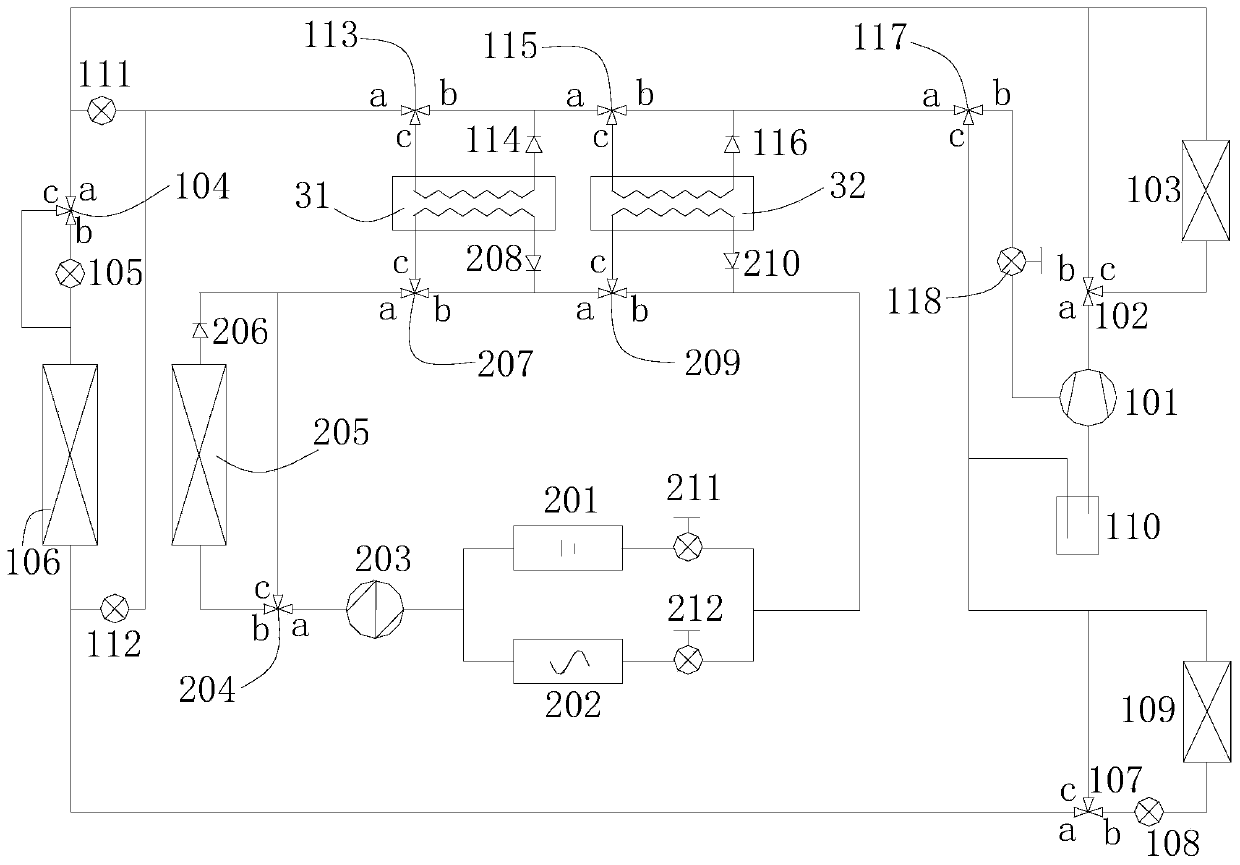
[0026] refer to figure 1 , is a thermal management system for electric vehicles, including a compressor 101, a cabin condenser 103, a first throttle valve 105, a first outdoor heat exchanger 106, a second throttle valve 108, a cabin evaporator Device 109, gas-liquid separator 110, third throttle valve 111, fourth throttle valve 112, heat accumulator 31, first check valve 114, first heat exchanger 32, second check valve 116, second A solenoid valve 118, a battery heat exchange module 201, a motor heat exchange module 202, a liquid pump 203, a second external heat exchanger 205, a third one-way valve 206, a fourth one-way valve 208, and a fifth one-way valve 210 , the second solenoid valve 211 and the third solenoid valve 212;

[0027] The compressor 101, the cabin condenser 103, the first throttle valve 105, the first outdoor heat exchanger 106, the second throttle valve 108, the cabin evaporator 109, and the gas-liquid separator 110 are connected in sequence, and the third sect...

Embodiment 2

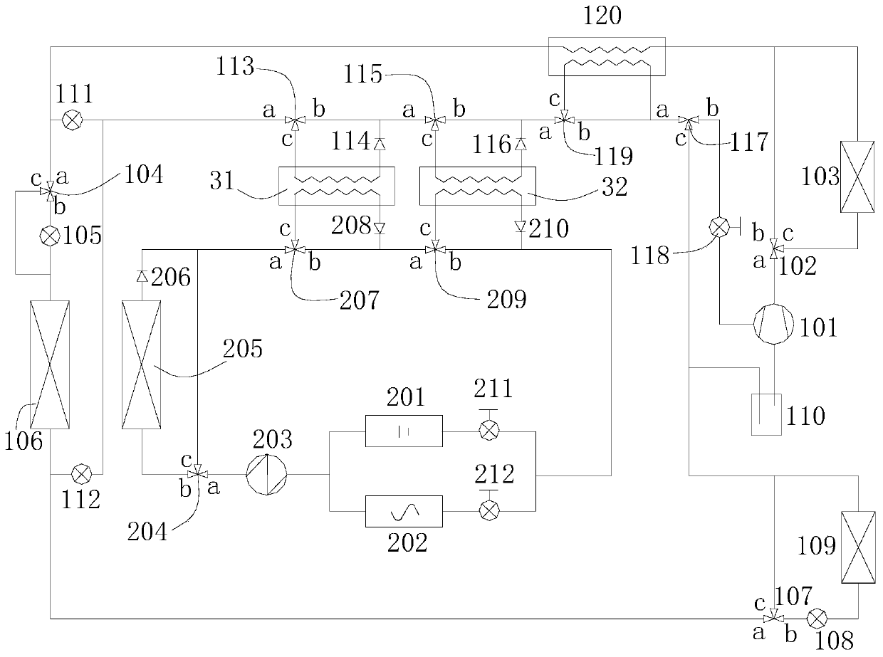
[0038] refer to figure 2 , is another thermal management system for electric vehicles. The difference between Embodiment 2 and Embodiment 1 is that: the air-conditioning heat pump system also includes a seventh three-way valve 119 and a second heat exchanger 120; the second heat exchanger The first inlet of the device 120 is connected with the outlet of the cabin condenser 103, the first outlet of the second heat exchanger 120, the first end of the second three-way valve 104 and the inlet of the third throttle valve 111 are connected; the seventh and third The first end of the through valve 119, the second end of the fifth three-way valve 115 and the outlet of the second one-way valve 116 are connected; the third end of the seventh three-way valve 119 is connected with the second inlet of the second heat exchanger 120 The second outlet of the second heat exchanger 120, the second end of the seventh three-way valve 119 and the first end of the sixth three-way valve 117 are con...


PUM


Abstract

The invention discloses a thermal management system used for an electric automobile. The thermal management system comprises an air conditioner heat pump system and a battery and motor heat conductionsystem. The air conditioner heat pump system comprises a compressor, a compartment condenser, a first extra-compartment heat exchanger, a compartment evaporator, a first heat exchanger, a heat accumulator, a gas-liquid separator and multiple valve bodies. The battery and motor heat conduction system comprises a battery heat exchange module, a motor heat exchange module, a liquid pump, a second extra-compartment heat exchanger, a second heat exchanger and multiple valve bodies. The air conditioner heat pump system and the battery and motor heat conduction system store and exchange energy through the heat accumulator and the first heat exchanger. Various thermal management modes of refrigerating, heating, dehumidification, heat dissipation of a battery and a motor and the like of the electric automobile can be achieved, and on the foundation that energy is saved, the comfort of a compartment and the safety of the battery and the motor are guaranteed.

Description

technical field [0001] The invention relates to the technical field of electric vehicles, in particular to a thermal management system for electric vehicles. Background technique [0002] With the improvement of battery technology, electric vehicles are gradually replacing traditional fuel-powered internal combustion engine vehicles and becoming the main development direction of new energy vehicles. There is a big difference in the thermal management needs of electric vehicles and internal combustion engine vehicles. Internal combustion engine vehicles use the air conditioning system to provide cooling for the cabin, and use the waste heat of the gas to heat the cabin. However, electric vehicles do not have the waste heat of gas to use, so new heating solutions must be sought. At the same time, in order to ensure the safety and life of the battery and motor, the temperature of the battery and motor must be controlled within a certain range, and an efficient heat dissipatio...

Claims


Application Information

Patent Timeline
Patent Type & Authority Applications(China)
IPC IPC(8): B60H1/00B60H1/14B60L58/26
CPCY02T10/70
Inventor 郭剑蒋方明王亦伟
Owner GUANGZHOU INST OF ENERGY CONVERSION - CHINESE ACAD OF SCI
Learn More