
Method for sealing composite wing wall panel and metal wing rib based on co-bonding process

A technology of composite materials and co-gluing, which is applied in the direction of household components, household appliances, and other household appliances, can solve the problems of prolonging assembly time, increasing sealing difficulty, and increasing production costs, so as to reduce assembly processes, improve sealing effect, Effect of production cost reduction

Active Publication Date: 2019-06-07
BEIJING AERONAUTIC SCI & TECH RES INST OF COMAC +1
View PDF6 Cites 3 Cited by
  • Summary
  • Abstract
  • Description
  • Claims
  • Application Information

AI Technical Summary

Problems solved by technology

The existing technology has the following disadvantages: when manufacturing glass fiber stoppers, it is necessary to separately manufacture conformal molds with the theoretical internal shape and surface characteristics of the skin for the glass fiber stoppers at different positions of the skin, generally egg-crate molds , the cost is high, and it needs to be cured separately, which increases the production cost; when the glass fiber stopper is assembled, it needs to be on four surfaces, the mating surface with the skin, the end surface of the two long stringer flanges of the wall plate, and the lower surface of the wing rib, respectively. Applying sealant prolongs the assembly time and increases the difficulty of sealing

Method used


Image

  • Method for sealing composite wing wall panel and metal wing rib based on co-bonding process
  • Method for sealing composite wing wall panel and metal wing rib based on co-bonding process
  • Method for sealing composite wing wall panel and metal wing rib based on co-bonding process

Examples


Embodiment Construction

[0030] Specific embodiments of the present invention will be described in detail below in conjunction with specific drawings. It should be noted that the technical features or combinations of technical features described in the following embodiments should not be regarded as isolated, and they can be combined with each other to achieve better technical effects. In the drawings of the following embodiments, the same reference numerals appearing in each drawing represent the same features or components, which can be applied in different embodiments.

[0031] The invention aims to solve the problems of cumbersome procedures and low efficiency in the prior art, which are caused by separate production of the sealing block and glue coating on all sides during sealing.

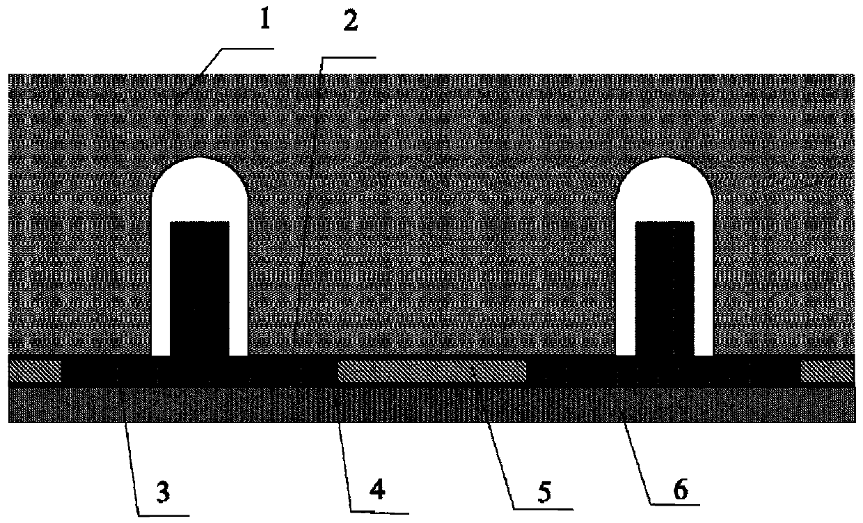
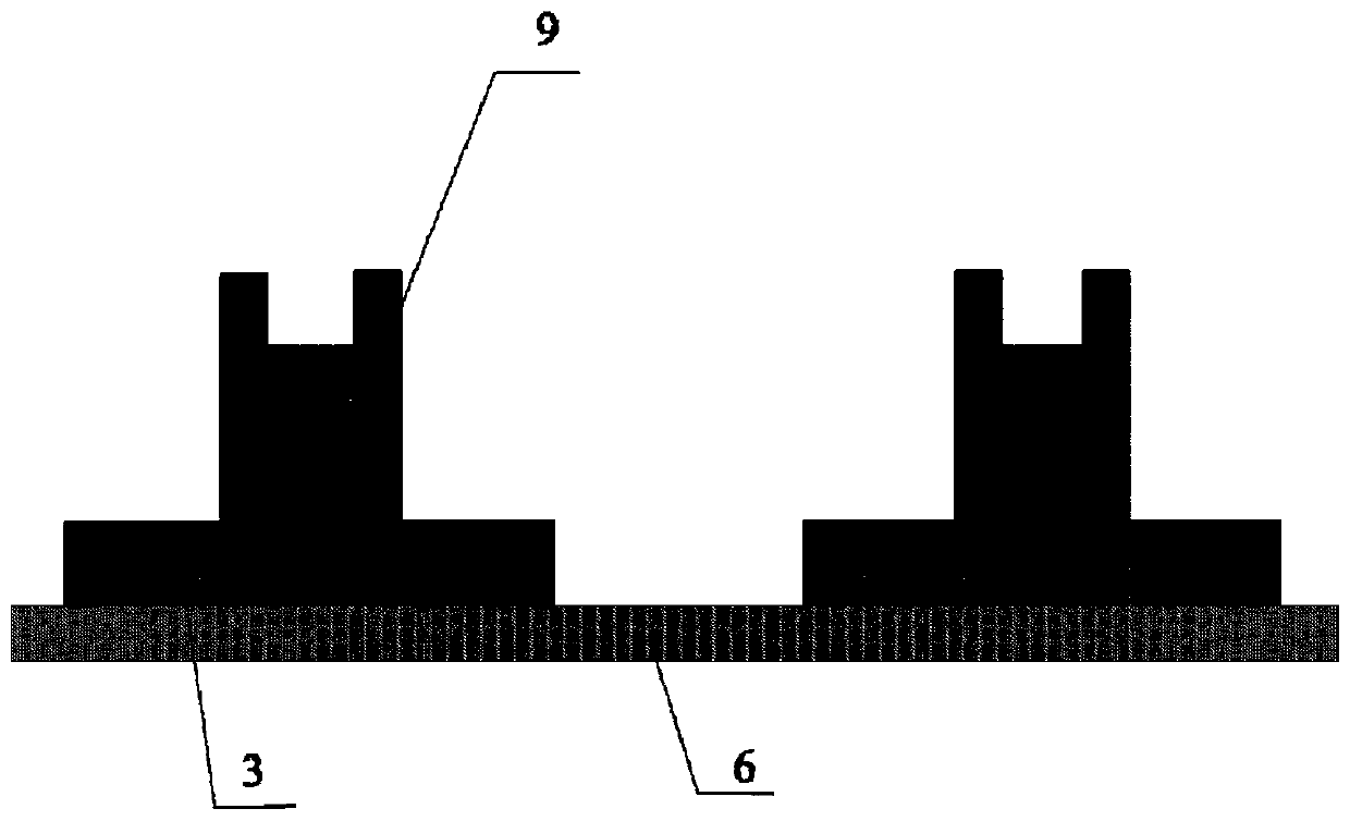
[0032] Such as Figure 4 , 5 As shown, the embodiment of the present invention is a method for sealing composite wing panels and metal ribs based on the co-gluing process, comprising the following steps: using glas...


PUM


Abstract

The invention relates to the technical field of aircraft body manufacturing, and provides a method for sealing a composite wing wall panel and a metal wing rib based on a co-bonding process. The method comprises the steps that agap formed by a stringer edge strip of the wing wall panel and the metal wing rib is filled with glass fibers, specifically, the glass fibers form a sealing stopper; the stringer edge strip and the sealing stopper are connected with skin simultaneously in a co-bonding mode, before being cured, resin between the sealing stopper and the stringer edge strip is heated and then naturally flows for filling, and no gap exists after curing of the resin; a stringer, the sealing stopper and the skin form an integral structure; and the matching faces of the sealing stopper andthe metal wing rib are glued and sealed. Compared with the prior art, there is no need to separately manufacture a follow-up mold with theskin theoretical inner profile characteristics for the stopper, only a maintenance rubber stop mold is maintained, resin does not need to be separately cured in a hot pressure tank, and thus the cost is reduced; the sealing glue only needs to be applied to thematching faces of the stopper and the wing rib instead of being applied to the periphery of the stopper, so that the assembly procedure is simplified, and the sealing effect is improved; and the method is simple and practical, and has broad application prospects.

Description

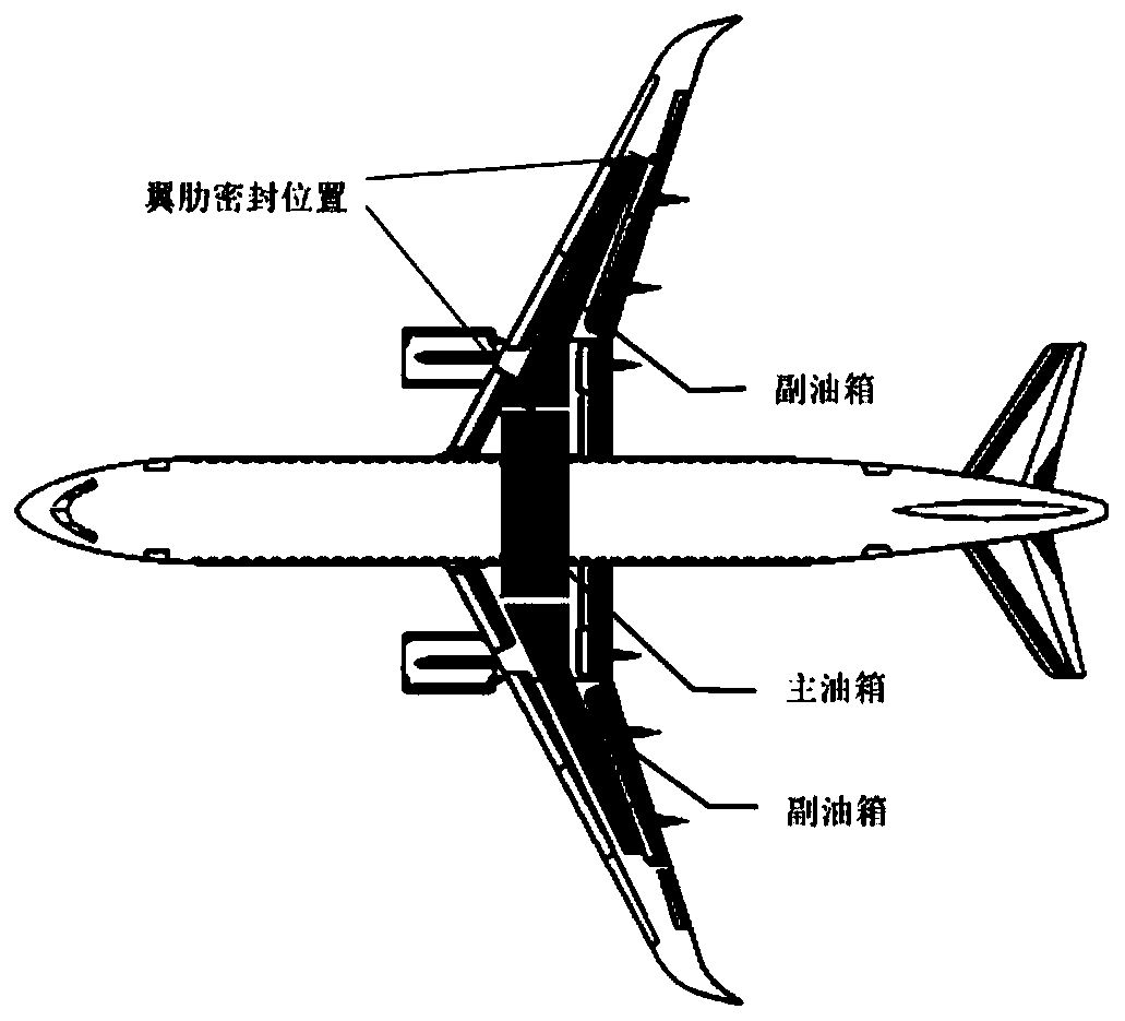
technical field [0001] The invention relates to the technical field of aircraft body manufacturing, in particular to a method for sealing composite material wing panels and metal wing ribs based on co-gluing technology. Background technique [0002] At present, due to the properties of high specific strength, high specific rigidity, designability, fatigue resistance, corrosion resistance, and less maintenance, carbon fiber reinforced composite materials have been widely used in the most advanced large civil aircraft in the world. The most typical application is the wing As for the wall structure, at present, large civil aircraft generally adopt a double-girder multi-rib structure. Due to the partition requirements of the wing fuel tank, some wing ribs are used as the fuel tank interface and need to be sealed, such as figure 1 shown. In addition, due to the bearing and structural form of the wing ribs, aluminum alloy materials are still mainly used at present. [0003] Bet...

Claims


Application Information

Patent Timeline
IPC IPC(8): B29C65/52B29L31/30
Inventor 孙见卓廖杰翠周俊彭志琦石林肖志鹏王栋刘传军
Owner BEIJING AERONAUTIC SCI & TECH RES INST OF COMAC
Learn More