


Quick Research
Generate reliable direction feasibility study reports for your R&D in just a few steps.

Technical Q&A
Discover and master advanced knowledge NOW. Basics, ideas, possibilities, all at once.

Find Solutions
As an expert in R&D theories, this can generate solutions to your technical problems instantly.

Evaluate Feasibility
Analyze your overall solution with one click, know your potential R&D risks in advance.

Monitor Landscape
Get weekly tech updates, stay abreast of the latest tech innovations and key insights.
Corrugated pipe molding machine and corrugated pipe production technology based on same
A corrugated pipe and forming machine technology, applied in the field of corrugated pipe production process and corrugated pipe forming machine, can solve the problems of water easily flowing to the chute and equipment failure, so as to increase the heat transfer efficiency, improve the efficiency and enhance the heat dissipation effect. Effect
- Summary
- Abstract
- Description
- Claims
- Application Information
AI Technical Summary
Problems solved by technology
Method used
Image

Examples
Embodiment 1
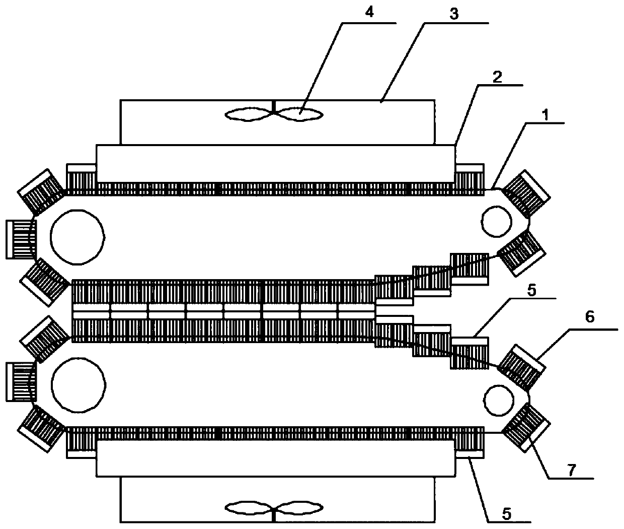
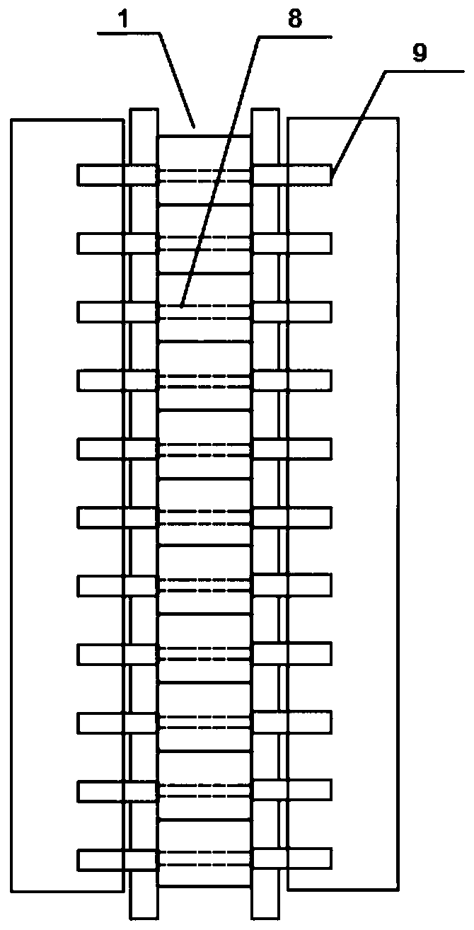
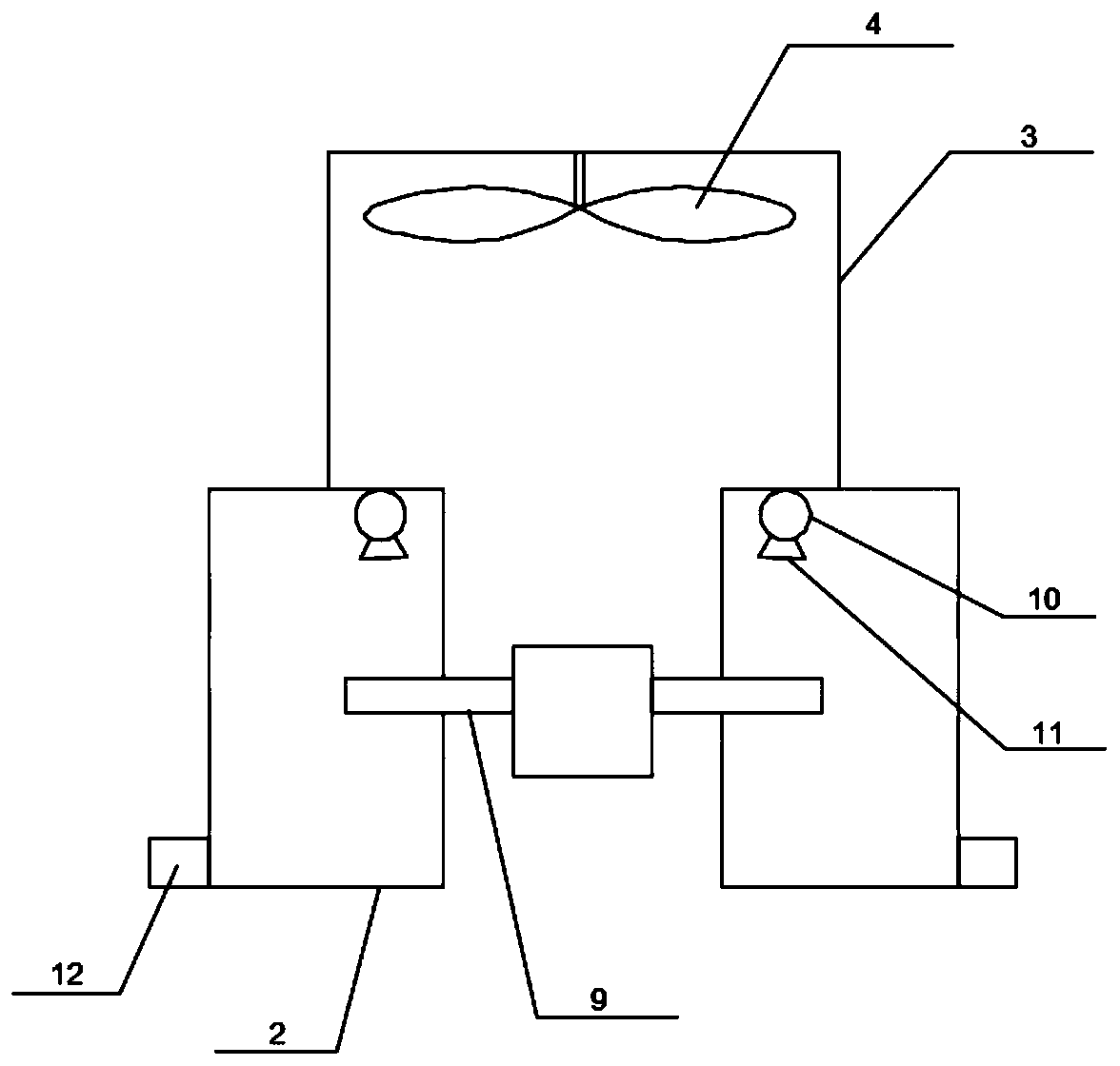
[0025] A corrugated pipe forming machine, including two circulating closed chute 1, a number of sliding seats 8 are installed on the chute 1, and a mold is installed on each sliding seat 8, and the molds on the two chute 1 cooperate to form during the movement Bellows forming channel, cooling boxes 2 are provided on both sides of the chute 1 away from the bellows forming channel, and cooling fins 9 are connected to both sides of each mold, and the side of the cooling box 2 close to the mold is along the mold movement direction A first notch is opened, and a second notch is opened at both ends of the cooling box 2, and the first notch communicates with the second notch, so that when the mold moves, the heat sink 9 enters the cooling box 2 from the second notch at one end of the cooling box 2 Then move along the first notch, and pass through the second notch at the other end; the top of the cooling box 2 is provided with a spray pipe 10 connected to an external water source, and ...
Embodiment 2
[0028] Based on Embodiment 1, the nozzles 11 are arranged along the moving direction of the mould, which is beneficial for the cooling fins 9 to repeatedly contact with the cooling water when they move in the cooling box 2, so that the cooling fins 9 can quickly cool down and increase the heat between the mold and the cooling fins 9. The transmission efficiency ensures that the mold reaches a lower temperature and improves the cooling and shaping efficiency of the bellows.
Embodiment 3
[0030] Based on Embodiment 1, the heat sink 9 is provided with evenly distributed capillary holes, so that a large number of small water droplets remain on the water-cooled heat sink 9, and these small water droplets are heated and evaporated when the mold is working, absorbing the heat on the heat sink 9, and enhancing heat dissipation The heat dissipation effect of the sheet 9 further improves the cooling and shaping effect of the bellows.
PUM
 Abstract
Description
Claims
Application Information
 - R&D Engineer
- R&D Manager
- IP Professional
- Industry Leading Data Capabilities
- Powerful AI technology
- Patent DNA Extraction
Browse by: Latest US Patents, China's latest patents, Technical Efficacy Thesaurus, Application Domain, Technology Topic, Popular Technical Reports.
© 2024 PatSnap. All rights reserved.Legal|Privacy policy|Modern Slavery Act Transparency Statement|Sitemap|About US| Contact US: help@patsnap.com