
Three-dimensional five-axle 3D laser cutting machine

A laser cutting machine, 3D technology, applied in the direction of laser welding equipment, welding equipment, metal processing equipment, etc., can solve the problems of laser cutting precision reduction, maintain a safe distance between the cutting head and the workpiece, and the large volume of linkage components, to reduce the laser The effect of energy loss, good overall sealing, and shortened optical path

Pending Publication Date: 2019-06-07
PENTA CHUTIAN LASER (WENZHOU) CO LTD
View PDF0 Cites 3 Cited by
  • Summary
  • Abstract
  • Description
  • Claims
  • Application Information

AI Technical Summary

Problems solved by technology

However, in large-scale laser cutting equipment, the cutting range of the laser cutting head is relatively large and the volume of its overall linkage components is relatively large. The spatial positioning is realized simply by changing the position of the laser cutting head, and the position adjustment path of the laser cutting head is complicated. It makes the laser cutting head unstable when adjusting its position, and the accuracy of laser cutting is reduced.
[0003] The position adjustment structure of the existing three-dimensional laser cutting machine is complex overall, which makes the adjustment path complicated, and the algorithm cannot accurately control the fixed-point adjustment angle to maintain a safe distance between the cutting head and the workpiece. The operator’s life is safe and fully automatic control is realized. The equipment operator inputs parameters to cut during operation, but the automatic control device is easy to cause equipment damage due to operator’s wrong parameters during operation. The existing 3D laser cutting machine is Equipment protection is not satisfactory

Method used


Image

  • Three-dimensional five-axle 3D laser cutting machine
  • Three-dimensional five-axle 3D laser cutting machine
  • Three-dimensional five-axle 3D laser cutting machine

Examples


Embodiment Construction

[0032] The present invention will be further described in detail below in conjunction with the accompanying drawings, embodiments and effect examples, without limiting the present invention.

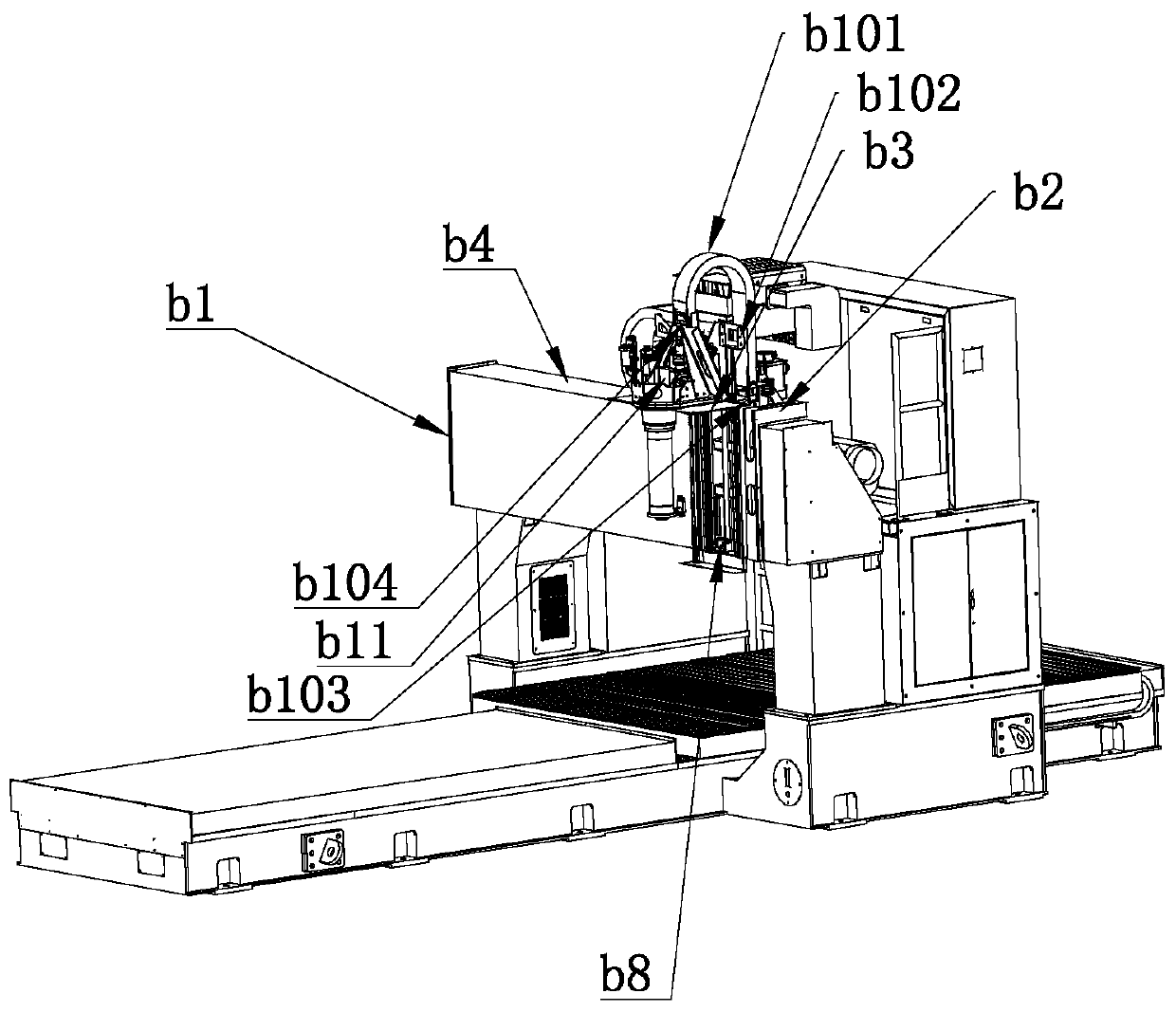
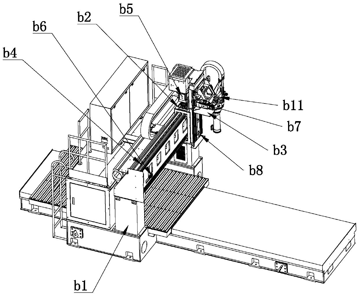
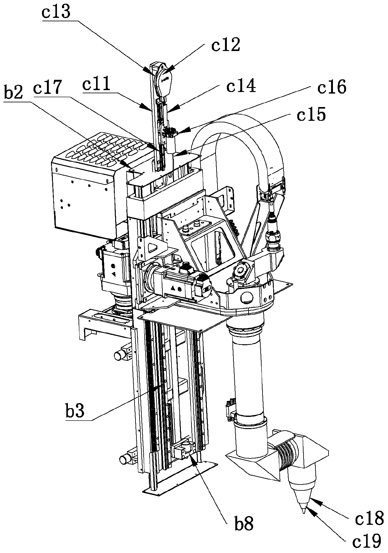
[0033] Such as Figure 1-14 As shown, a three-dimensional five-axis 3D laser cutting machine includes a base a1, a workbench a2, a mounting frame and a cutting head. The workbench a2 is slidably connected to the base a1, and the drive workbench a2 is arranged inside the base a1. A single-axis sliding drive device, the base a1 is provided with a first anti-collision block a3, the first anti-collision block a3 is a position proximity switch, and the first anti-collision block a3 is used to detect the movement of the workbench a2 position, the installation position of the first anti-collision block a3 defines the sliding travel range of the table a2, and the first anti-collision block a3 is coupled with the driving device, and the driving device includes a single-axis sliding direction of t...


PUM


Abstract

The invention discloses a three-dimensional five-axle 3D laser cutting machine. The machine comprises a base, a worktable, a mounting frame and a cutting head; the worktable is slidingly connected with the base; the adjustment of the laser cutting head in three-dimensional five-axle directions is realized through a Y-axle mounting frame, a Z-axle mounting frame, a C-axle pipeline and a B-axle pipeline; the C-axle pipeline and the B-axle pipeline are connected with a cutting head main body through a right-angled joint; a reflecting mirror and a zooming lens module are arranged in the right-angled joint; a total optical path is shortened; the laser energy loss is reduced; collision preventing blocks are arranged in three-dimensional directions for limiting the moving travel of the cutting head; the Y-axle mounting frame is provided with a protecting mechanism for protecting the Z-axle mounting frame; the moving travel on a Z axle is limited through a tension value; and the laser cuttingmachine is more compact in overall structure and simpler in multi-directional angle control method algorithm, improves the control precision, and is provided with multiple protections for protecting equipment to prolong the service life of the equipment.

Description

technical field [0001] The invention relates to the field of laser cutting, in particular to a three-dimensional five-axis 3D laser cutting machine. Background technique [0002] High-power laser cutting has become the mainstay equipment for sheet metal processing today, and its high processing efficiency and high precision are widely favored by the market. With the improvement of workpiece cutting requirements, the cutting requirements have been improved from two-dimensional cutting to three-dimensional cutting. Robotic three-dimensional cutting can meet the requirements of low precision and efficiency in the above fields with its advanced, flexible and fast flexible processing characteristics. , but for the processing of devices with relatively high precision and efficiency requirements, especially for the cutting and processing of three-dimensional workpieces with complex spatial surfaces, the existing ordinary three-dimensional laser cutting machines usually use laser cu...

Claims


Application Information

Patent Timeline
IPC IPC(8): B23K26/38B23K26/70
CPCY02P70/10
Inventor 吴让大李正张业芝
Owner PENTA CHUTIAN LASER (WENZHOU) CO LTD
Learn More