Pressure controlling valve to be attached to base-mounted change valve

A technology of pressure regulating and switching valves, which is applied in the field of pressure regulating valves and can solve problems such as the inability to use elevators

Inactive Publication Date: 2003-01-08
SMC CORP
View PDF4 Cites 0 Cited by
  • Summary
  • Abstract
  • Description
  • Claims
  • Application Information

AI Technical Summary

Problems solved by technology

Therefore, different fluid pressures will be supplied to the two pressure chambers 55a and 55b of the cylinder 55 of the lifter 55 constituting the load 56 used for lifting and lowering, so that the use method of keeping the lifter balanced in its position cannot be adopted.

Method used


Image

  • Pressure controlling valve to be attached to base-mounted change valve
  • Pressure controlling valve to be attached to base-mounted change valve
  • Pressure controlling valve to be attached to base-mounted change valve

Examples


Embodiment Construction

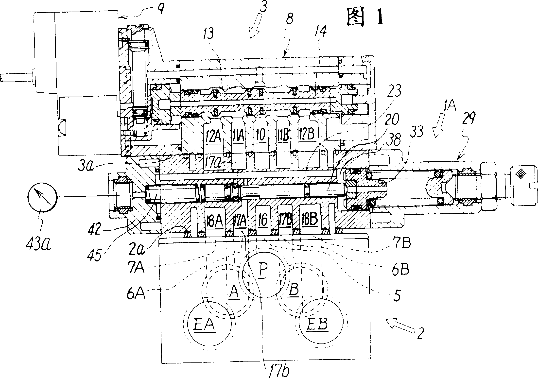
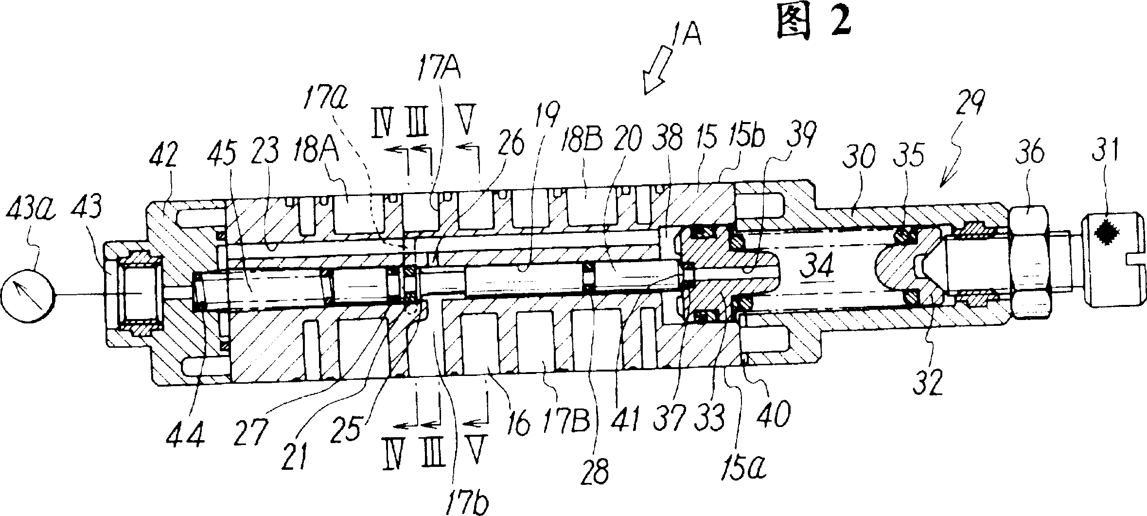
[0041] FIG. 1 shows a state in which a pressure regulating valve 1A according to a first embodiment of the present invention is directly installed between a base 2 and a switching valve 3 . These respective members 1A, 2 and 3 are fixed to each other by appropriate mounting structures such as mounting bolts (not shown).

[0042]The above-mentioned base 2 is a general term for components such as a manifold and a bottom plate with a piping port. It has a structure that can mount one or more switching valves. The base 1 shown in the figure is for mounting one switching valve 3 and Monolithic base used. The base 2 has a compressed air supply port P, a first discharge port EA, and a second discharge port EB on one side, and has a first output port A and a second output port B on the other side. . Also, on the upper surface of the above-mentioned base 2, a flat mounting surface 2a for a pressure regulating valve is provided; on this mounting surface 2a, supply through-holes 5, whi...


PUM


Abstract

A pressure-regulating valve 1A has a valve body 15 which contains a plurality of communication passages that allow opposed through-holes in the transfer valve 3 and base 2 to communicate, a pressure-regulating valve hole 19 which traverses these communication passages, a pressure-regulating valve stem 20 inserted into the valve hole, and means for cooperating with the pressure-regulating valve stem 20 in regulating the pressure in an output communication passage 17A or 17B to a set value. The valve 1A is mounted in such a way as to be directly sandwiched between a transfer valve 3 and a base 2, and the valve body 15 has substantially the same breadth as the transfer valve 3.

Description

technical field [0001] The present invention relates to a pressure regulating valve, and more particularly to a pressure regulating valve mounted on a base-mounted switching valve for regulating the pressure of a fluid output from the switching valve to a desired pressure. Background technique [0002] When the fluid pressure machine is driven by the pressure fluid such as compressed air supplied through the switch valve, due to the difference in the set pressure and operating state of the machine, sometimes it is necessary to adjust the pressure of the fluid supplied to the fluid pressure machine. Make adjustments. When adjusting the fluid pressure in this way, it is common to install a pressure regulating valve such as a pressure reducing valve on the piping connecting the output port of the changeover valve and the fluid pressure equipment. [0003] However, since known pressure regulating valves are generally large in size, when such a pressure regulating valve is conne...

Claims


Application Information

Patent Timeline
IPC IPC(8): F15B13/00F15B13/04F15B13/043F15B13/08G05D16/10
CPCF15B13/0832F15B13/0402F15B13/0431F15B13/0814G05D16/10F15B2013/041F15B13/0896G05D16/101Y10T137/87885Y10T137/87169Y10T137/261F16K31/122
Inventor 田岛正道胜田博行石川诚
Owner SMC CORP
Why Eureka
Try Eureka