Connector mechanism for card

A connection device and notch technology, which is applied to the parts of the connection device, the device for connecting, connecting/disconnecting the connecting parts, etc. The effect of small horizontal and wide size

Inactive Publication Date: 2009-05-27
ALPS ALPINE CO LTD
View PDF4 Cites 0 Cited by
  • Summary
  • Abstract
  • Description
  • Claims
  • Application Information

AI Technical Summary

Problems solved by technology

[0006] Recently, machines such as mobile phones equipped with this kind of card connecting device have a tendency to be miniaturized, and thereupon, a smaller card connecting device is desired, but in the above-mentioned prior art, due to supporting The elastic holding piece on the sliding member is arranged on the side of the moving path of the card, and the elastic holding piece is inserted into the notch of the card from the side in the state where the card is inserted, so there is space for the elastic holding piece to make the card The problem that the width dimension of the connection device becomes large

Method used


Image

  • Connector mechanism for card
  • Connector mechanism for card
  • Connector mechanism for card

Examples


Embodiment Construction

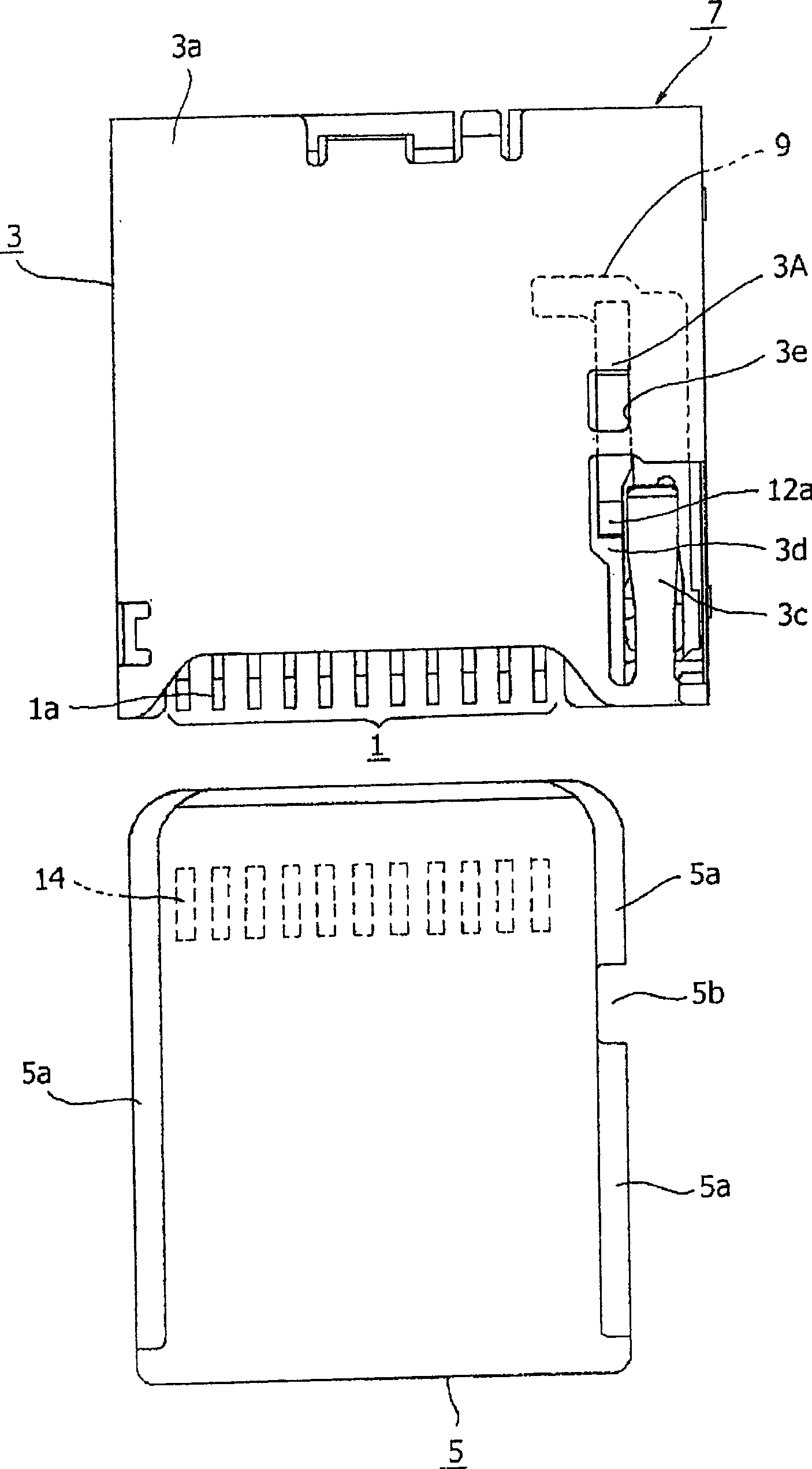
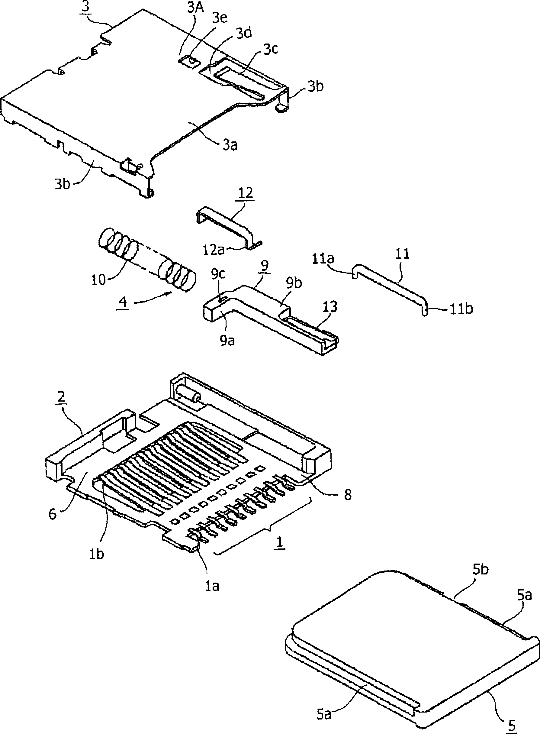
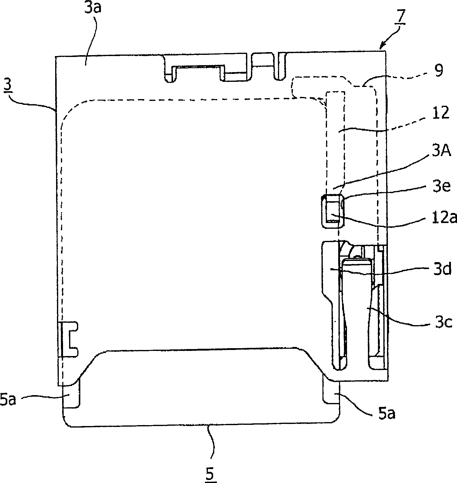
[0020] Embodiments of the invention will be described with reference to the drawings, figure 1 It is a plan view of the card connector device according to the embodiment of the present invention, figure 2 is an exploded perspective view of the card connector, image 3 It is a plan view showing the card insertion completion state of the card connecting device, Figure 4 It is a plan view showing the state in which the card insertion is completed with the cover member removed from the card connector, Figure 5 This is an explanatory diagram of the operation of the card connector.

[0021] As shown in these drawings, the card connection device of this embodiment is roughly constituted by the following parts: a base member 2 made of synthetic resin supporting a plurality of terminal members 1; and a metal plate covering the upper open end of the base member 2. The cover part 3 made of the system; the card ejection mechanism 4 housed inside the bottom part 2.

[0022] The base...


PUM


Abstract

The invention provides a connector device for a card capable of reducing its width. On the connector device for a card in which a card 5 having a notched part 5b at its edge part of upper face side can be inserted, a slide member 9 for energizing the card 5 in ejection direction by engaging with a front end part of the card is arranged in a housing 7 having a card housing part 6, an elastic holding piece 12 is fixed to the slide member 9 in cantilever form so as to overlap with a sliding passage of the card in a plane, and an engaging part 12a formed to the free end side of the elastic holding piece 12 is made to fit in the notched part 5b from upside of the card.

Description

technical field [0001] The present invention relates to a card connecting device for connecting a card with information storage function, and in particular to a card connecting device for holding a card inserted into a case at a predetermined installation position by an elastic holding piece. Background technique [0002] Conventionally, it is known that as this kind of card connecting device, it is equipped with a sliding member that is engaged with a card inserted in the housing and is movable along the insertion and ejection directions of the card, and that the sliding member is applied to the card ejection direction. The coil spring with a strong force, and the elastic holding piece supported on the above-mentioned sliding member in a cantilever shape. When the card is inserted, the elastic holding piece is fitted into the notch of the side edge of the card from the side to stably hold the card at the mounting position in the case (for example, refer to Patent Document 1...

Claims


Application Information

Patent Timeline
Patent Type & Authority Patents(China)
IPC IPC(8): H01R13/62H01R13/187H01R13/639G06K17/00
Inventor 川端隆志我妻透佐藤一树
Owner ALPS ALPINE CO LTD
Why Eureka
Try Eureka