U-shaped hollow electric heating radiant tube

A radiant tube and electric heating technology, applied in ohmic resistance heating parts, heating element shapes, ohmic resistance electrodes, etc., can solve problems such as inability to form effective air circulation channels, slow heat dissipation, and rupture of heating radiant tubes, and reduce high temperature. Oxidation effect, prolonging service life, heating power improvement effect

Pending Publication Date: 2019-06-04
江苏金达电热电器有限公司
View PDF5 Cites 0 Cited by
  • Summary
  • Abstract
  • Description
  • Claims
  • Application Information

AI Technical Summary

Problems solved by technology

[0005] (3) The wall thickness of the electric heating tube casing of this structure is thicker, the surface load is large, and no effective air circulation channel can be formed inside, the heat dissipation is relatively slow, and the internal temperature is too high during use, which is easy to cause internal expansion and cause the heating radiant tube If it is not cooled with the furnace during cooling, the cooling time is obviously longer. If you want to speed up the cooling process, or you need to install another cooling device or cooling tube next to the furnace, use the cooling device to heat the electric heating tube after use. For cooling, additional equipment investment is added;
[0006] (4) Due to the temperature gradient between the internal heating resistance wire, the thicker casing and the ambient temperature, due to the influence of thermal inertia, the temperature control area of ​​the electric heating tube is relatively large, for example, the actual required furnace The temperature is 900°C, and in order to achieve the required furnace temperature, the actual temperature of the resistance wire must reach 950-1000°C during gradual heating, and the temperature in the furnace will gradually rise to more than 900°C. , the heating temperature of the resistance wire needs to be lowered, but due to thermal inertia, the temperature reduction is always carried out gradually; on the contrary, when the temperature in the furnace becomes lower, the heating temperature of the resistance wire needs to be increased; therefore, the actual temperature in the furnace It is difficult to maintain a stable temperature at around 900°C. The greater the thickness of the heating tube and the quality of the material, the greater the influence of thermal inertia and the smaller the temperature control accuracy (the temperature control range is relatively large, generally ±30°C)
[0007] Therefore, the sleeve-type electric heating rod commonly used in the field of industrial electric heating at present has a large amount of materials, high cost, high energy consumption, large surface load and difficult heat dissipation, which is inconsistent with the green industrial production concept advocated by the country; and the temperature control accuracy It's not very good either, and it can't meet the increasing needs of customers

Method used


Image

  • U-shaped hollow electric heating radiant tube
  • U-shaped hollow electric heating radiant tube
  • U-shaped hollow electric heating radiant tube

Examples


Embodiment Construction

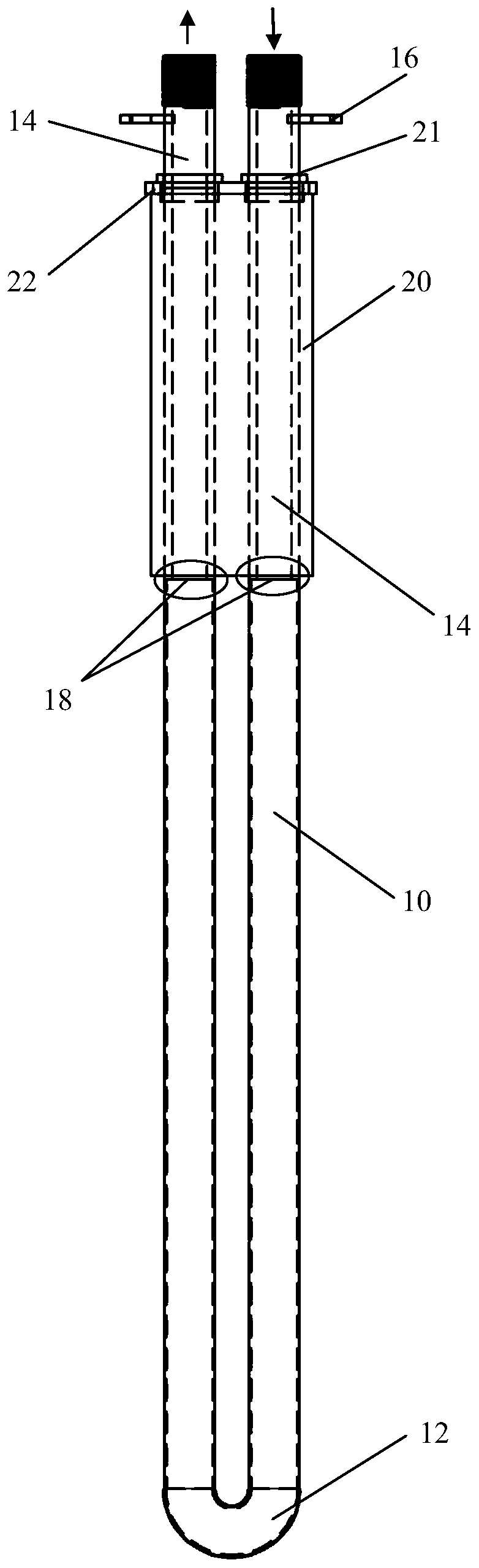
[0021] refer to figure 1 The structure diagram of the U-shaped hollow tube electric heating radiant tube of the present invention is shown. The electric heating radiant tube includes a pair of hollow heating tube bodies 10, and one end of the tube body 10 is connected and penetrated to form a U The connection part 12 of the type structure, the connection pipe 14 (electrode lead-out pipe) connected with the other end of the pipe body 10, the periphery of part of the connection pipe 14 is provided with a heat preservation section 20 composed of heat preservation material, and the connection pipe 14 is connected with the heat preservation section 20 There is a fixed plate 22 for fixing the heating radiant tube and the boiler; the end of the connecting tube 14 is provided with a threaded structure 142, which is convenient for connecting with the cooling tube; the connecting tube 14 is respectively provided with electrode connecting terminals 16 , connected to the positive and nega...


PUM


Abstract

The invention provides a U-shaped hollow electric heating radiant tube, which comprises hollow heating tube bodies arranged in a pair, a connecting portion, connecting tubes, a thermal insulation section and a fixing plate, wherein the connecting portion connects and communicates one end portions of the tube bodies to form a U-shaped structure, the connecting tubes are connected with the other ends of the tube bodies, the thermal insulation section composed of a thermal insulation material is arranged on the peripheries of parts of the connecting tubes, and the fixing plates for fixing the heating radiant tube and a boiler are arranged at joints of the hollow heating tube bodies and the connecting tubes; the end portions of the connecting tubes are provided with threaded structures; the connecting tubes are respectively provided with electrode connecting terminals which are connected with positive and negative electrodes of a power supply; and the joints of the hollow heating tube bodies and the connecting tubes are welded and connected with joints of connecting portion and the hollow heating tube bodies by means of circumferential seam fully welding. The U-shaped hollow electric heating radiant tube directly adopts the electric heating alloy to form the hollow heating tubes, and the weight of the material is only about 20% of the original, thereby significantly reducing the material cost, and significantly reducing the energy consumption required for heating; and the temperature control precision is high, the service life is long, and the heating power is high.

Description

technical field [0001] The invention relates to the technical field of industrial electric heating, in particular to a U-shaped hollow tube electric heating radiant tube. Background technique [0002] In the current field of industrial electric heating technology, for example, in the field of industrial boiler heating, electric heating rods with a U-shaped structure are generally used. One or more heating resistance wires are placed inside the U-shaped sleeve, and the resistance wires are fixed on the Inside the casing, the manufacturing process of this kind of electric heating tube is relatively mature. Although there are many process steps, it is relatively easy and convenient to manufacture, so it is widely used, but this kind of electric heating tube also has many problems: [0003] (1) The structure of casing + built-in resistance wire is adopted, resulting in a large amount of material and quality of the electric heating tube. The weight of a set of heating tubes is 50...

Claims


Application Information

Patent Timeline
Patent Type & Authority Applications(China)
IPC IPC(8): H05B3/40H05B3/02H05B3/03
Inventor 倪高金陆秀栋
Owner 江苏金达电热电器有限公司
Why Eureka
Try Eureka