
A cut-off wavelength shifted single-mode fiber

A technology of single-mode fiber and cut-off wavelength, which is applied in the field of optical communication, can solve problems such as large mode field diameter, and achieve the effects of large mode field diameter, low bending loss, and low manufacturing cost

Active Publication Date: 2020-08-18
ZHONGTIAN TECH ADVANCED MATERIALS CO LTD +4
View PDF6 Cites 0 Cited by
  • Summary
  • Abstract
  • Description
  • Claims
  • Application Information

AI Technical Summary

Problems solved by technology

However, the existing optical fiber structure design is difficult to achieve a large mode field diameter (≥12.0m) and meet other requirements of the G.654E standard at the same time

Method used


Image

  • A cut-off wavelength shifted single-mode fiber
  • A cut-off wavelength shifted single-mode fiber
  • A cut-off wavelength shifted single-mode fiber

Examples


Embodiment Construction

[0027] In the following description, a lot of specific details are set forth in order to fully understand the present invention, but the present invention can also be implemented in other ways different from those described here, and those skilled in the art can do it without departing from the meaning of the present invention. Similar applications, therefore, the present invention is not limited by the specific embodiments disclosed below.

[0028] It should be noted that the refractive index difference in the present invention refers to the difference between the refractive index of each corresponding part in the optical fiber and the refractive index of the outer cladding.

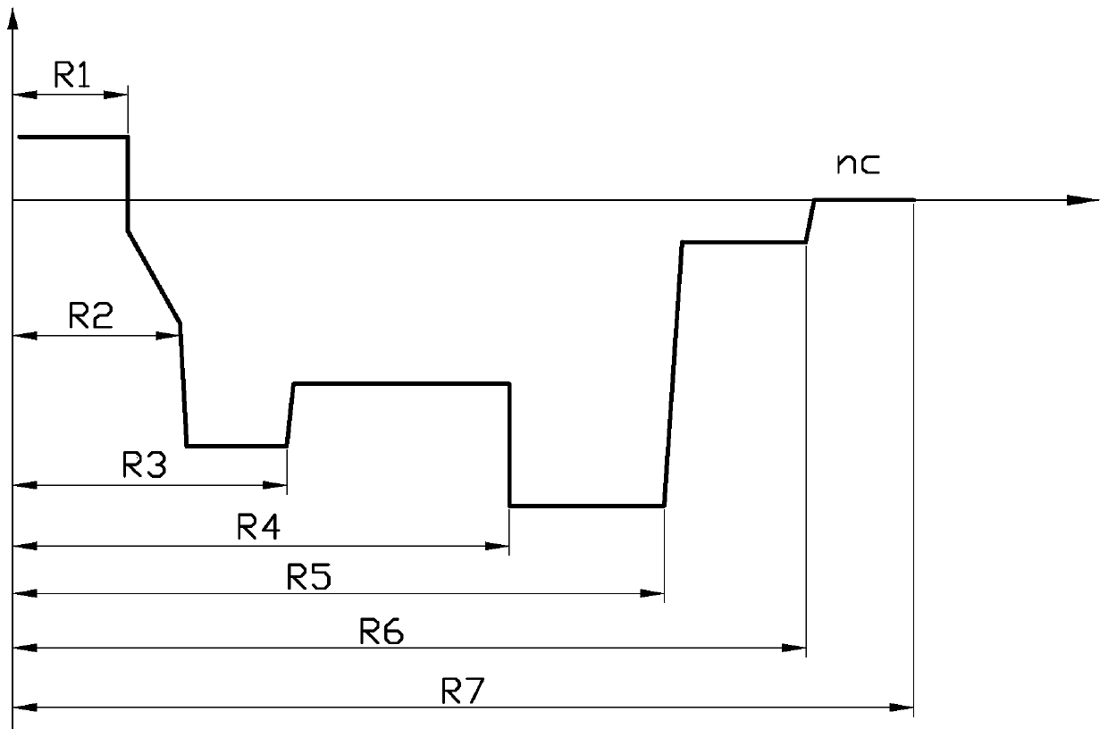
[0029] see figure 1 , figure 1 It is a schematic diagram of the structural design of the cut-off wavelength shifted single-mode optical fiber of the embodiment of the present invention. The optical fiber is a G.654E single-mode optical fiber, and its mode field diameter, optical cable cut-off waveleng...


PUM

PropertyMeasurementUnit
radiusaaaaaaaaaa
thicknessaaaaaaaaaa
radiusaaaaaaaaaa

Abstract

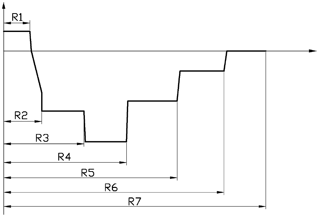
The invention provides a cut-off wavelength shift single-mode optical fiber. The cut-off wavelength shift single-mode optical fiber comprises a fiber core, a gradient layer, an inner cladding, a platform layer, a concave cladding, a transition layer and an outer cladding which are sequentially arranged from inside to outside, wherein the radius R1 of the fiber core ranges from 4 to 8 mu m, and therefractive index difference delta n1 of the fiber core ranges from 0 to 0.15%, the radius of the gradient layer is R2, the thickness R2-R1 ranges from 0.5 to 4 mu m, and the refractive index difference delta n2 of the gradient layer ranges from delta n1 to delta n3; the radius of the inner cladding is R3, the thickness R3-R2 ranges from 4 to10 mu m, and the refractive index difference delta 3 ofthe inner cladding ranges from -0.15% to -0.35%; the radius of the platform layer is R4, the thickness R4-R3 ranges from 6 to 20 mu m, and the refractive index difference delta n4 of the platform layer ranges from -0.15% to -0.35%; the radius of the concave cladding is R5, the thickness R5-R4 ranges from 5 to 15 mu m, the refractive index difference delta n5 ranges from -0.3% to -0.45%, and the delta n5 is less than the delta n4; the radius of the transition layer is R6, the thickness R6-R5 ranges from 0 to 15 mu m, and the refractive index difference delta n6 of the transition layer ranges from 0 to -0 .1%; and the radius R7 of the outer cladding ranges from 60 to 65 mu m. The cut-off wavelength shift single-mode optical fiber provided by the invention has the advantages of low attenuation coefficient, low bending loss, large mode field diameter and low manufacturing cost, and meets the parameter requirements of the G.654E optical fiber.

Description

technical field [0001] The invention relates to the technical field of optical communication, in particular to a cut-off wavelength shifted single-mode optical fiber. Background technique [0002] The optical fiber communication network is constantly developing towards the "three super" directions of ultra-long distance, ultra-large capacity, and ultra-high speed. In recent years, 400Gbs high-speed optical fiber communication technology has begun to enter the practical field. However, in the construction of long-distance backbone networks, the existing G.652 optical fiber can no longer meet the requirements of 400Gbs technology. In order to adapt to and promote the needs of the rapid development of optical fiber communication systems, the relevant performance indicators of optical fibers as the transmission medium of optical fiber communication networks need to be further improved and optimized. [0003] For 400Gbs high-speed optical fiber communication technology, the loss...

Claims


Application Information

Patent Timeline
Patent Type & Authority Patents(China)
IPC IPC(8): G02B6/036
Inventor 蒋新力范艳层沈一春郑福生李伟华邓黎赵威孙绍辉
Owner ZHONGTIAN TECH ADVANCED MATERIALS CO LTD
Learn More