
Bridge damage positioning method based on standing vehicle test

A damage location and damage location technology, which is applied in the analysis of solids by using sonic/ultrasonic/infrasonic waves, which can solve the problems of a large number of sensors, finite element models, and inconvenient implementation, so as to improve the localization efficiency, and the data analysis process is simple and applicable. sexual effect

Active Publication Date: 2019-06-04
HEFEI UNIV OF TECH
View PDF11 Cites 12 Cited by
  • Summary
  • Abstract
  • Description
  • Claims
  • Application Information

AI Technical Summary

Problems solved by technology

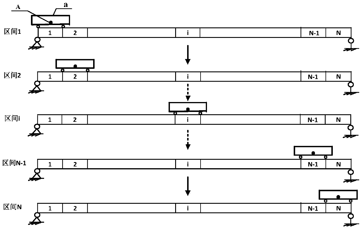
[0004] In order to avoid the shortcomings of the above-mentioned prior art, the present invention provides a method for locating bridge damage based on static vehicle testing. By testing two-axle vehicles, they are gradually placed at different positions of the bridge to determine the frequency of the bridge damage. Solve the problems that traditional methods require finite element models, inconvenient implementation, difficult data processing and a large number of sensors

Method used


Image

  • Bridge damage positioning method based on standing vehicle test
  • Bridge damage positioning method based on standing vehicle test
  • Bridge damage positioning method based on standing vehicle test

Examples


Embodiment 1

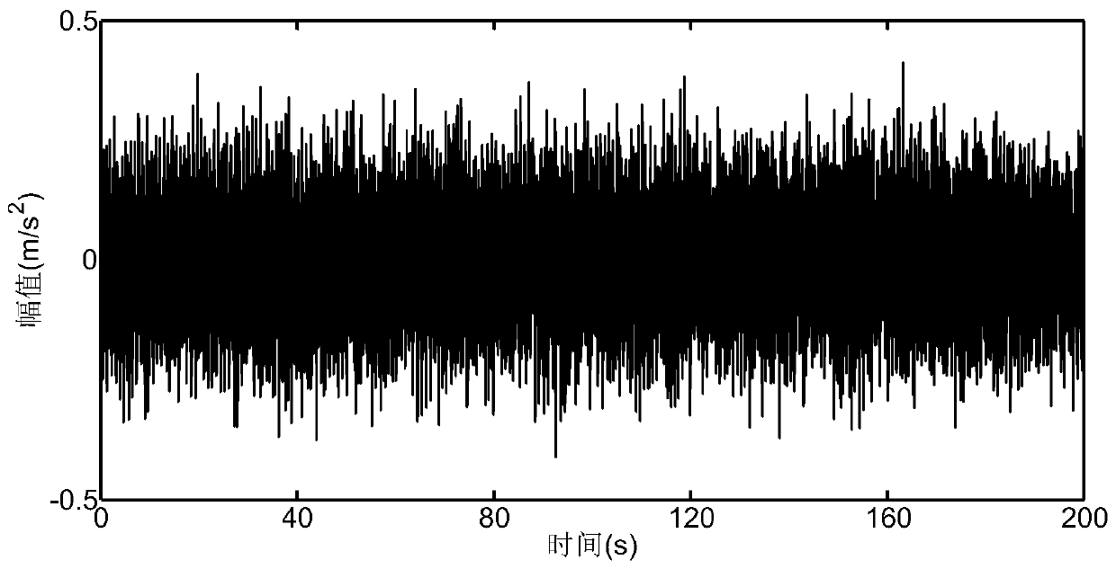
[0055] figure 2 The simply supported beam is shown with a length of 20m and a modulus of elasticity of 7.5×10 10 N / m 2 , with a density of 2.7 × 10 3 kg / m 3 , the cross section is a square section, the side length is 0.2m, and it is divided into 30 intervals at equal intervals. By means of numerical simulation, it is divided into 20 plane Euler beam elements for simulation, the sampling frequency is 100Hz, and the time is 200s. Using random excitation, the dynamic response of the beam is calculated by the Newmark-β method. This embodiment considers the following two working conditions:

[0056] (1) Single damage condition: interval 17, the section stiffness is reduced to 70% of the original value;

[0057] (2) Double damage condition: In interval 12, the section stiffness is reduced to 80% of the original value; in interval 20, the section stiffness is reduced to 75% of the original value.

[0058] Identification steps:

[0059] S1: Select a two-axle vehicle a with a ...

Embodiment 2

[0066] Figure 7 The two-span continuous beam cantilever beam shown, the length of each span is 15m, other parameters, solution method and identification process are the same as in Example 1, and two working conditions are also considered:

[0067] (1) Single damage condition: interval 23, the section stiffness is reduced to 80% of the original value;

[0068] (2) Double damage condition, in interval 10, the section stiffness is reduced to 70% of the original value, and in interval 23, the section stiffness is reduced to 75% of the original value. The positioning results under the single-damage condition and the double-damage condition are as follows: Figure 8 and Figure 9 shown.

[0069] Embodiments 1 and 2 verify that the method of the present invention adopts a single acceleration sensor for testing. By moving the position of the two-axle vehicle and measuring multiple system frequencies, damage localization can be effectively achieved through the constructed positioni...


PUM


Abstract

The invention discloses a bridge damage positioning method based on a standing vehicle test. The method is characterized in that a single wireless acceleration sensor is installed on a two-axle vehicle to form a movable test device; the two-axle vehicle is gradually placed at different positions of a bridge for testing, and dynamic responses of the two-axle vehicle and a bridge system under environmental excitation are obtained; spectrum analysis is performed on the dynamic responses through Fourier transform to obtain a corresponding frequency; and system frequency variation curves when the two-axle vehicle is located at different positions before and after damages are compared to determine a damage position of the bridge. The method can be conveniently implemented, efficiency is high anda result is visual. Problems that a traditional damage positioning method requires a large number of test sensors, testing is complicated and data processing is difficult are effectively solved.

Description

technical field [0001] The invention relates to the field of beam structure monitoring and detection, and more specifically relates to a bridge damage location method based on static vehicle testing, and the identification result can be used to evaluate the safety state of the bridge. Background technique [0002] Bridges are critical hubs in traffic engineering. During the follow-up service, the bridge is eroded by various complex environments, such as typhoons, earthquakes, floods, corrosion, explosions, etc., as well as the long-term repeated effects of increasing vehicle load and traffic flow. Material aging, fatigue, damage accumulation, and performance degradation gradually bring huge hidden dangers to the safe operation of bridge structures, which also highlights the necessity and urgency of condition monitoring and damage identification in the process of bridge structure operation. [0003] At present, the health monitoring of bridge structures has become an importa...

Claims


Application Information

Patent Timeline
Patent Type & Authority Applications(China)
IPC IPC(8): G01N29/12
Inventor 贺文宇任伟新王佐才
Owner HEFEI UNIV OF TECH
Learn More