Method for performing interphase current sharing of iLLC resonant converter and prolonging power-down maintenance time

A resonant converter and power transformer technology, which is applied in power electronics technology and its application fields, can solve the problems that the current balance adjustment of the out-of-phase resonant cavity cannot be satisfied at the same time, the resonant inductor can no longer be integrated, and the power-off maintenance time is prolonged. The effect of prolonging the electrical holding time, reducing the volume and reducing the edge effect

Active Publication Date: 2019-05-28
东莞市全普电气科技有限公司
View PDF2 Cites 5 Cited by
  • Summary
  • Abstract
  • Description
  • Claims
  • Application Information

AI Technical Summary

Problems solved by technology

The invention patent "A Current Sharing Regulation Method for Interleaved Parallel LLC Resonant Circuits" (201810195443.9) adopts the detection of the current or voltage error of each LLC branch, and adjusts the duty ratio of each LLC branch according to the error to adjust the gain of each LLC branch to realize Current sharing, which is a control method to adjust the pulse width, can solve the current sharing problem, but it does not help to prolong the power-off maintenance time
However, this method can no longer integrate the resonant inductor into the transformer, which increases the size of the converter
[0007] None of the methods given in the above documents and patents can simultaneously meet the needs of phase-staggered resonant cavity current balance adjustment and extended power-off maintenance time.

Method used


Image

  • Method for performing interphase current sharing of iLLC resonant converter and prolonging power-down maintenance time
  • Method for performing interphase current sharing of iLLC resonant converter and prolonging power-down maintenance time
  • Method for performing interphase current sharing of iLLC resonant converter and prolonging power-down maintenance time

Examples


Embodiment Construction

[0047] The following will clearly and completely describe the technical solutions in the embodiments of the present invention with reference to the accompanying drawings in the embodiments of the present invention. Obviously, the described embodiments are only some, not all, embodiments of the present invention. Based on the embodiments of the present invention, all other embodiments obtained by persons of ordinary skill in the art without making creative efforts belong to the protection scope of the present invention.

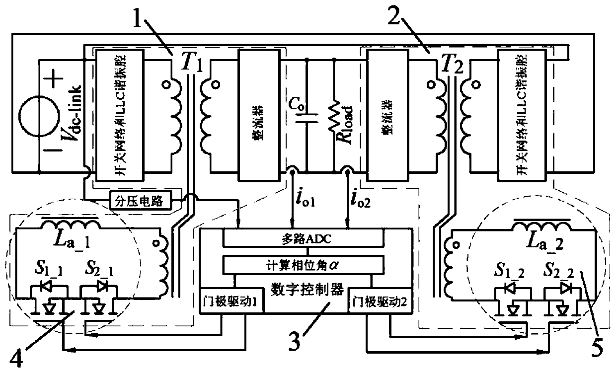
[0048] Such as figure 1 As shown, an iLLC resonant converter includes a first LLC resonant converter 1 and a second LLC resonant converter 2 with identical parameters and structures, a digital controller 3 for realizing phase-to-phase current sharing and power-off maintenance time extension control, The parameters and structures are identical to the first switch control inductor 4 and the second switch control inductor 5, and an auxiliary winding is respective...


PUM


Abstract

The invention provides an iLLC resonant converter. The iLLC resonant converter comprises two LLC resonant converters, a digital controller and two switch control inductors. The power transformers of the two LLC resonant converters are respectively provided with an auxiliary winding, wherein the two switch control inductors are respectively connected with the auxiliary winding in parallel, the parameters and the structure of the two LLC resonant converters are the same, the input ends of the two LLC resonant converters are connected in parallel, the output ends of the two LLC resonant converters are also connected in parallel, and the parameters and the structure of the two switch control inductors are the same. According to the resonant converter provided by the invention, respective output current and common input voltage of the two LLC resonant converters are sampled through the digital controller. The phase angle of the inductor is controlled by the operation adjusting switch to realize current sharing of the resonant cavity current, the direct current voltage gain of the resonant cavity can be adjusted according to the direct current bus voltage during input power failure, andthe power failure maintenance time of the converter is prolonged.

Description

technical field [0001] The invention relates to the field of power electronics technology and its application, in particular to an iLLC resonant converter and a method for sharing current between phases and prolonging power-off maintenance time. Background technique [0002] The output voltage of switching power supply such as server group power supply and communication power supply is low, and the output current is relatively large, and the power supply is required to maintain a normal constant voltage output of more than ten milliseconds after the power grid is powered off, so that the uninterruptible power supply (UPS) can operate during this period Provide backup energy for these power sources. This period of ten milliseconds is called the hold-up time. The LLC resonant converter is an inductance-inductor-capacitor series resonant DC-DC converter with a narrow frequency range and a wide voltage regulation range. It can realize zero-voltage soft switching in the full loa...

Claims


Application Information

Patent Timeline
IPC IPC(8): H02M3/28H02M3/335
CPCH02M3/28H02M3/335Y02B70/10
Inventor 赵振兴
Owner 东莞市全普电气科技有限公司
Why Eureka
Try Eureka