C-type pneumatic chuck and production method thereof

A pneumatic chuck and chuck technology, which is applied in the field of machinery, can solve the problems that the lifting and lowering of the slip body cannot achieve synchronous operation, the connection strength of the main body of the chuck is low, and the service life is short. The effect of long life and high connection strength

Pending Publication Date: 2019-05-28
江苏佰恰利机械有限公司
View PDF5 Cites 1 Cited by
  • Summary
  • Abstract
  • Description
  • Claims
  • Application Information

AI Technical Summary

Problems solved by technology

At present, most of the chuck main bodies in pneumatic chucks are integrally formed by special molds. The process is difficult and the size deviation is large. The formed chuck body has low connection strength and short service life

Method used


Image

  • C-type pneumatic chuck and production method thereof
  • C-type pneumatic chuck and production method thereof
  • C-type pneumatic chuck and production method thereof

Examples


Embodiment Construction

[0046] The technical solutions in the embodiments of the present invention will be clearly and completely described below with reference to the accompanying drawings in the embodiments of the present invention. Obviously, the described embodiments are only a part of the embodiments of the present invention, rather than all the embodiments. Based on the embodiments of the present invention, all other embodiments obtained by those of ordinary skill in the art without creative efforts shall fall within the protection scope of the present invention.

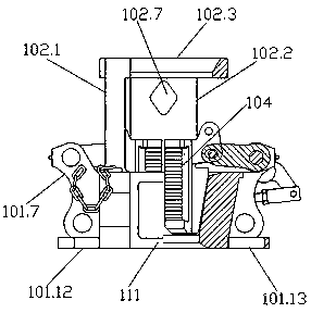
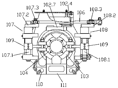
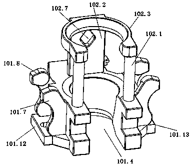
[0047] see Figure 1-Figure 3 , The present invention relates to a C-type pneumatic chuck, including a chuck body, a slip body 103 and a power mechanism, the chuck body includes a base 101 and a centralizer 102, and a tooth plate is arranged in the slip body 103 104, the power mechanism includes a cylinder assembly 105, a connecting rod 106 driven by the cylinder assembly 105, a left crankshaft assembly 107 connected with the connect...


PUM

PropertyMeasurementUnit
hardnessaaaaaaaaaa

Abstract

The invention relates to a C-type pneumatic chuck. The C-type pneumatic chuck comprises a chuck main body, a slip body and a power mechanism, wherein the chuck main body comprises a base and a centering frame, an insert is arranged in the slip body; the power mechanism comprises a cylinder assembly, a connecting rod driven by the cylinder assembly, a left crank assembly connected with the connecting rod, and a right crank assembly connected with the connecting rod; the left crank assembly comprises a left shaft, a left crank arm and a left connecting shaft; the right crank assembly comprises aright shaft, a right crank arm and a right connecting shaft; the left connecting shaft and the right connecting shaft are both fixedly connected with the connecting rod; the left shaft and the rightshaft are respectively fixedly connected with the slip body through a rotating arm; a valve is connected between a left front section and a right front section of the base through a valve pin. The C-type pneumatic chuck has the advantages of being low in processing and manufacturing difficulty, high in connecting strength, long in service life, and convenient to mount.

Description

technical field [0001] The invention relates to a C-type pneumatic chuck and a production method thereof, belonging to the technical field of machinery. Background technique [0002] Pneumatic chucks are mainly used for holding drill pipe, tubing, casing and other pipe strings in oil and natural gas workover operations. At present, most of the chuck bodies in the pneumatic chucks are made by integral molding with special molds, which are difficult to process and have large dimensional deviations. The formed chuck main body has low connection strength and short service life. Therefore, a new technical solution is required to solve the above-mentioned technical problems. SUMMARY OF THE INVENTION [0003] The purpose of the present invention is to overcome the above-mentioned deficiencies, and to provide a C-type pneumatic chuck and its production method with low manufacturing difficulty, high strength, long service life and convenient installation. [0004] The purpose of...

Claims


Application Information

Patent Timeline
Patent Type & Authority Applications(China)
IPC IPC(8): E21B19/10B22C9/22B22C9/06B23P15/00B23P23/06
Inventor 王万华秦旭蒋栋
Owner 江苏佰恰利机械有限公司
Why Eureka
Try Eureka