Chemical sludge concentration treatment device and treatment process thereof

A chemical sludge and treatment device technology, applied in sludge treatment, water/sludge/sewage treatment, flocculation/sedimentation water/sewage treatment, etc. Problems such as the volume occupancy rate of large sludge tanks, to achieve the effect of improving operating efficiency, increasing processing capacity, and reducing volume occupancy rate

Inactive Publication Date: 2019-05-28
东莞顺裕纸业有限公司
View PDF9 Cites 0 Cited by
  • Summary
  • Abstract
  • Description
  • Claims
  • Application Information

AI Technical Summary

Problems solved by technology

[0002] At present, in the recycled paper and papermaking industry, with the triple requirements of policy, economy and environmental protection, enterprises need to implement clean production, energy saving and emission reduction. The content of organic matter with high concentration and refractory biodegradation is increasing, and the biochemical treatment process commonly used at home and abroad can no longer meet the discharge water discharge standard, so the advanced treatment system is widely used
However, improper chemical sludge concentration treatment will lead to high water content after concentration, which does not meet the requirements of sludge concentration in the subsequent sludge treatment system, increases the volume occupancy rate of the sludge tank, and reduces the operation of the sludge treatment system. efficiency

Method used


Image

  • Chemical sludge concentration treatment device and treatment process thereof

Examples


Embodiment Construction

[0016] In order to make the object, technical solution and advantages of the present invention clearer, the present invention will be further described in detail below in conjunction with the accompanying drawings and embodiments. It should be understood that the specific embodiments described here are only used to explain the present invention, not to limit the present invention.

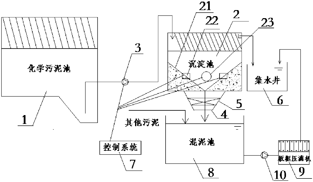
[0017] A kind of chemical sludge thickening treatment device of the present invention, such as figure 1 As shown, it includes a chemical sludge tank 1, one end of the bottom of the chemical sludge tank 1 sinks, and the sinking position inside the chemical sludge tank 1 is connected to the sedimentation tank 2 through a first pipeline, and the first pipeline is provided with There is a water pump 3, a stirring device 23 is provided at the side of the middle height of the sedimentation tank 2, and a slant plate 21 is provided at the bottom of the sedimentation tank 2, and several sludge leakage holes...


PUM


Abstract

The invention belongs to the technical field of sludge treatment, and particularly relates to a chemical sludge concentration treatment device, which comprises a chemical sludge pool, wherein one endof the bottom of the chemical sludge pool downwards sinks; the downwards sinking position inside the chemical sludge pool is connected with a precipitation pool through a first pipeline; a water pumpis arranged on the first pipeline; a stirring device is arranged in the side surface position of the middle height of the precipitation pool; an inclined plate is arranged at the bottom of the precipitation pool; a plurality of sludge leaking holes are uniformly formed in the inclined plate; a position sensor is arranged on the middle part of the inclined plate; a second pipeline communicated withthe precipitation pool is arranged under the precipitation pool; an electromagnetic valve is arranged on the second pipeline; a sludge mixing pool is arranged right under the second pipeline; a watercollecting well is communicated with the top of the precipitation pool through a pipeline; the sludge mixing pool is communicated with a plate frame press filter through a pipeline with a second water pump; the outlet end of the plate frame press filter is connected with a water collecting well through a pipeline; a control system is respectively and electrically connected with the water pump, the position sensor and the stirring device. The invention also provides a treatment method of the chemical sludge concentration treatment device.

Description

technical field [0001] The invention belongs to the technical field of sludge treatment, and in particular relates to a chemical sludge concentration treatment device and a treatment process thereof. Background technique [0002] At present, in the recycled paper and papermaking industry, with the triple requirements of policy, economy and environmental protection, enterprises need to implement clean production, energy saving and emission reduction. The content of organic matter with high concentration and refractory biodegradation is increasing, and the current biochemical treatment process commonly used at home and abroad can no longer meet the discharge water discharge standard, so the advanced treatment system is widely used. However, improper chemical sludge concentration treatment will lead to high water content after concentration, which does not meet the requirements of sludge concentration in the subsequent sludge treatment system, increases the volume occupancy rat...

Claims


Application Information

Patent Timeline
IPC IPC(8): C02F1/52C02F11/122
Inventor 田锦明曾文智张琳赖耀康
Owner 东莞顺裕纸业有限公司
Why Eureka
Try Eureka