
Tilting-type hydraulic machine

A hydraulic machine and hydraulic rod technology, applied in the field of hydraulic lifts, can solve the problems of not increasing the friction between the user and the lifting platform, not being able to adjust the inclination angle well, and not being able to extend the workbench well, etc. Achieve the effects of reducing limitations, increasing convenience, and reducing shaking

Inactive Publication Date: 2019-05-28
JIN HOUNG FUH (CHUZHOU) CONVEYING EQUIP CO LTD
View PDF5 Cites 5 Cited by
  • Summary
  • Abstract
  • Description
  • Claims
  • Application Information

AI Technical Summary

Problems solved by technology

[0003] The retrieved application number is CN201520971308.0, which is a fixed hydraulic lift that is easy to move. It includes a base; a supporting platform is located on both sides of the base, and the support arms are arranged on both sides of the base; The four corners of the four corners are respectively provided with limit columns. When the hydraulic lift is in the lowest state, the bearing platform is erected on the limit columns, and connecting holes are respectively provided on the limit columns. The workbench in the technology disclosed in the above patent cannot be well The extension is not convenient for the user to use in different situations, it is extremely inconvenient to use, and the friction between the user and the lifting platform cannot be increased well during the use process, which may easily cause the user to slip and fall. The inclination angle cannot be adjusted well for different needs

Method used


Image

  • Tilting-type hydraulic machine
  • Tilting-type hydraulic machine
  • Tilting-type hydraulic machine

Examples


Embodiment Construction

[0029] The following will clearly and completely describe the technical solutions in the embodiments of the present invention with reference to the accompanying drawings in the embodiments of the present invention. Obviously, the described embodiments are only some, not all, embodiments of the present invention. Based on the embodiments of the present invention, all other embodiments obtained by persons of ordinary skill in the art without making creative efforts belong to the protection scope of the present invention.

[0030] It should be noted that when a component is said to be "fixed" to another component, it can be directly on the other component or there can also be an intervening component. When a component is said to be "connected" to another component, it may be directly connected to the other component or there may be intervening components at the same time. When a component is said to be "set on" another component, it may be set directly on the other component or t...


PUM


Abstract

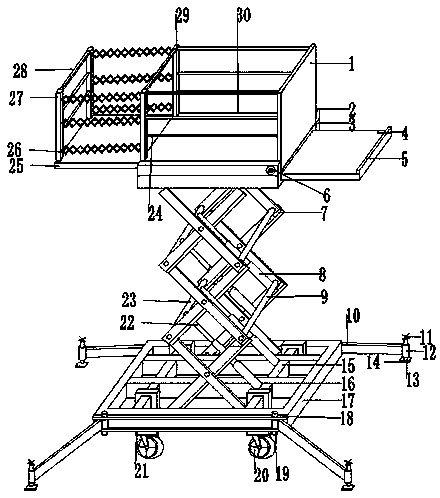
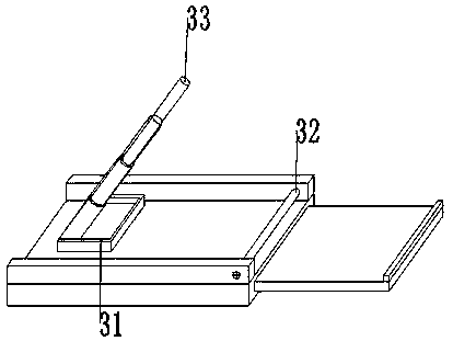
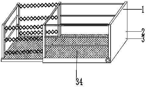
The invention discloses a tilting-type hydraulic machine. The tilting-type hydraulic machine comprises an elevator base frame and a base. A U-shaped plate is fixed to the top of the base through bolts. A third hydraulic rod is fixed to the inner wall of one side of the U-shaped plate through bolts. Side baffles are fixed to the two sides of the outer wall of the top of the base through bolts respectively. A rotary rod is fixed to the inner wall, on the side opposite to the other side baffle, of each of the two side baffles through bolts. A hollow bottom plate is arranged on the outer wall of the top of the base. A baffle is fixed to the outer wall of one side of the bottom plate through bolts. A rotary sleeve is arranged at one end of the bottom plate. An extension bas plate is arranged inside the hollow part of the bottom plate in an insertion connection manner. According to the tilting-type hydraulic machine, the working area can be well broadened through the extension bottom plate,the limitation on the working area is reduced, a base plate can play a good role in supporting a workbench when the workbench inclines, a wear-proof antiskid pad can play a good role in skid prevention, supporting bottom plates can keep stable well during work, shakes are lessened, and therefore, an elevator can be more stable in work.

Description

technical field [0001] The invention relates to the technical field of hydraulic lifts, in particular to a tiltable hydraulic machine. Background technique [0002] Elevator is a lifting mechanical equipment or device for a platform or a semi-enclosed platform that carries people or goods up and down the vertical passageway. It is a whole consisting of platforms and the equipment, motors, cables and other auxiliary equipment used to manipulate them. [0003] The retrieved application number is CN201520971308.0, which is a fixed hydraulic lift that is easy to move. It includes a base; a supporting platform is located on both sides of the base, and the support arms are arranged on both sides of the base; The four corners of the four corners are respectively provided with limit columns. When the hydraulic lift is in the lowest state, the bearing platform is erected on the limit columns, and connecting holes are respectively provided on the limit columns. The workbench in the t...

Claims


Application Information

Patent Timeline
Patent Type & Authority Applications(China)
IPC IPC(8): B66F11/04
Inventor 费贵龙许静郭方其王亮亮
Owner JIN HOUNG FUH (CHUZHOU) CONVEYING EQUIP CO LTD
Learn More