
Roller type heat cutting-off mechanism

A thermal cutting, roll-type technology, applied in the direction of object supply, electrolyte battery manufacturing, sustainable manufacturing/processing, etc., can solve problems such as inability to cut, temperature drop, etc., and achieve the effect of preventing re-adhesion

Pending Publication Date: 2019-05-28
SHENZHEN GDLASER TECH CO LTD
View PDF0 Cites 2 Cited by
  • Summary
  • Abstract
  • Description
  • Claims
  • Application Information

AI Technical Summary

Problems solved by technology

For working conditions that require multi-layer thermal cut-off, the temperature of the thermal resistance wire drops after cutting several layers of diaphragms, which is lower than the minimum temperature that can cut off the diaphragms, resulting in the failure of cutting the remaining layers

Method used


Image

  • Roller type heat cutting-off mechanism
  • Roller type heat cutting-off mechanism
  • Roller type heat cutting-off mechanism

Examples


Embodiment Construction

[0026] In order to fully understand the technical content of the present invention, the technical solutions of the present invention will be further introduced and illustrated below in conjunction with specific examples, but not limited thereto.

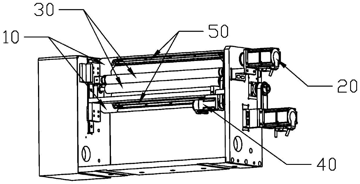
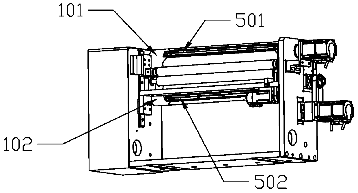
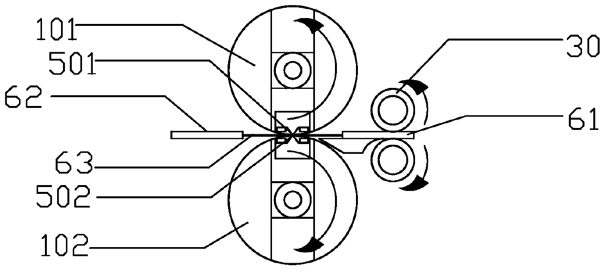
[0027] Such as Figure 1 to Figure 3 As shown, a roller thermal cut-off mechanism includes a feed roller 10, a feed power device 20, a discharge roller 30 and a discharge power device 40, the feed roller 10 is connected with the feed power device 20, and the discharge roller 30 is connected with the discharge power device 40, the feed roller 10 is provided with a thermal cutting wire 50, the discharge roller 30 is arranged in front of the feed roller 10, the first lamination unit 61 enters the feed roller 10 and Driven by the roller 10, it advances to the discharge roller 30. After the first lamination unit 61 passes through the feed roller 10 completely, the thermal cutting wire 50 cuts off the diaphragm 63 connected between the two...


PUM


Abstract

The invention provides a roller type heat cutting-off mechanism. The roller type heat cutting-off mechanism comprises feeding rollers, a feeding power device, discharging rollers and a discharging power device; the feeding rollers and the feeding power device are connected; the discharging rollers and the discharging power device are connected; heat cutting wires are arranged on the feeding roller; the discharging rollers are arranged in front of the feeding rollers; a first stack unit enters the feeding rollers and moves forwards to the discharging rollers under driving of the feeding rollers; after the first stack unit completely passes through the feeding rollers, the heat cutting wires cut off a membrane connected between two stack units; and the discharging rollers drive the first stack unit to be transported to a next station. The heat cutting wires are installed on the feeding rollers and embedded in the surfaces of the feeding rollers, the heat cutting wires can rotate with thefeeding rollers, and cutting off is finished while feeding is performed. The heat cutting wires are installed on the upper and lower feeding rollers, the cutting-off efficiency is high, and a multi-layer membrane structure can be cut off.

Description

technical field [0001] The invention relates to the technical field of cutting equipment, and more specifically refers to a roller-type thermal cutting mechanism. Background technique [0002] In the existing lithium battery lamination technology, the efficiency of bag lamination is relatively high. The bag-making lamination is to align the upper and lower sides of the negative electrode sheet with the separator, and make a negative electrode sheet bag after hot pressing around it, then cut off the separator, and then alternately laminate with the positive electrode sheet. Among them, the diaphragm cutting method is mainly thermal cutting. [0003] The existing thermal cutting mechanism is mainly composed of a feed roller, a thermal resistance wire, an air cylinder, and a discharge roller. The feed roller transports the diaphragm to the inside of the thermal cutting knife assembly. When the position to be cut on the diaphragm is directly below the thermal resistance wire, ...

Claims


Application Information

Patent Timeline
IPC IPC(8): B26F3/12B26D7/32B65H5/06H01M10/058
CPCY02E60/10Y02P70/50
Inventor 何林郑新华
Owner SHENZHEN GDLASER TECH CO LTD
Learn More