
Safety protection device for EPS fire-fighting emergency power supply

A safety protection device and fire emergency technology, which is applied in the direction of emergency power arrangement, circuit device, substation/switch layout details, etc., can solve problems that affect the use effect, maintenance may cause safety hazards, and emergency power supply problems, etc., to improve protection effect, improved stability, improved practical effect

Pending Publication Date: 2019-05-24
志纳电器有限公司
View PDF0 Cites 0 Cited by
  • Summary
  • Abstract
  • Description
  • Claims
  • Application Information

AI Technical Summary

Problems solved by technology

[0004] At present, the EPS emergency power supply box is usually installed against the wall. The traditional EPS emergency power supply box is formed by welding or bolting of multiple plates. The components of the emergency power supply are installed in a special emergency power supply box, and the emergency power supply box is provided for user operation. In the side opening, there is a suitable door hinged, and the door is locked by a common mechanical lock; however, simply protecting the emergency power supply components in the EPS emergency power supply box through the door cannot achieve good protection. Protection effect, it is easy to cause problems with the emergency power supply, affect the use effect, and easily cause safety hazards during the maintenance process

Method used


Image

  • Safety protection device for EPS fire-fighting emergency power supply
  • Safety protection device for EPS fire-fighting emergency power supply
  • Safety protection device for EPS fire-fighting emergency power supply

Examples


Embodiment Construction

[0039] The safety protection device for EPS fire emergency power supply will be further explained with reference to the accompanying drawings.

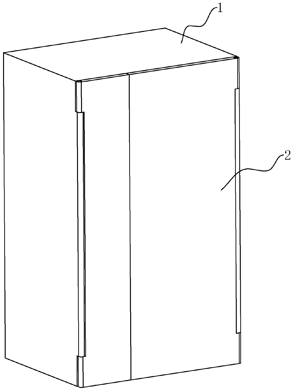
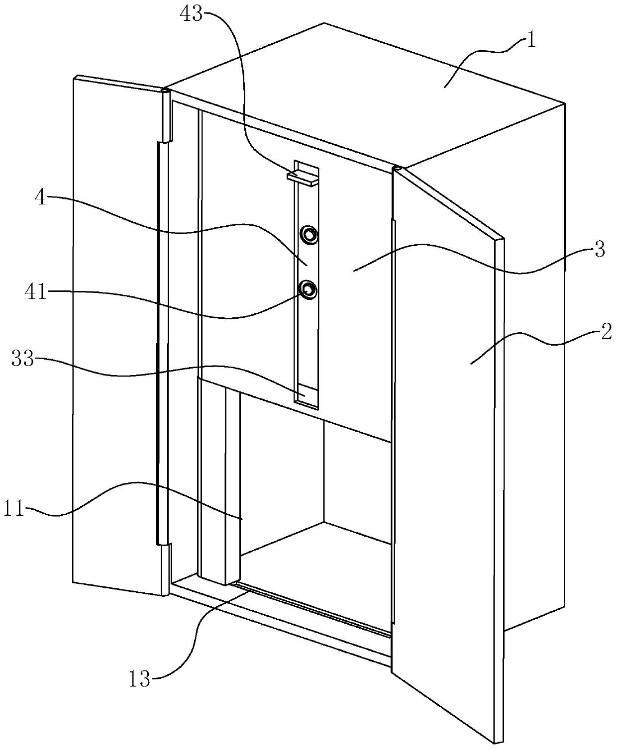
[0040] A safety protection device for EPS fire emergency power supply, such as figure 1 with figure 2 As shown, the emergency power supply box 1 and the box door 2 for installing various parts of the emergency power supply including the hollow structure are provided; The side is hinged on one side of the opening 11, so that it can be adapted to achieve the effect of closing the emergency power supply box 1.

[0041] Such as figure 2 with Image 6As shown, wherein, a fixed plate 3 is provided above the opening 11, the fixed plate 3 is arranged between the box door 2 and the emergency power supply, and one side of the fixed plate 3 is hinged on the side wall of the opening 11; The other side of the fixed plate 3 is fixedly provided with a magnet one 31, and on the other side wall of the opening 11, a magnet two 12 corresponding to...


PUM


Abstract

The invention discloses a safety protection device for an EPS fire-fighting emergency power supply, and relates to the technical field of fire-fighting equipment. The safety protection device comprises an emergency power supply box with a hollow structure, an opening communicated with the inner cavity is formed in the emergency power supply box; a box door matched with the opening is hinged to oneside of the opening; a fixed plate is arranged in the opening; and an operation plate is arranged on the fixed plate in a directional sliding manner. When the fixed plate and the operation plate areunfolded, the opening is shielded. An operation button is arranged on one end surface of the operation panel; an operation switch connected / disconnected with an emergency power supply part in the emergency power supply box is arranged on the other end surface of the operation panel; the operation button is electrically connected with the operation switch. The EPS emergency power supply box has theadvantages that the protection effect of all parts of the emergency power supply in the EPS emergency power supply box is improved, the practical effect of the EPS emergency power supply box is improved, and the safety and the stability during maintenance are improved.

Description

technical field [0001] The invention relates to the technical field of fire-fighting equipment, more specifically, it relates to a safety protection device for EPS fire-fighting emergency power supply. Background technique [0002] EPS (Fire Emergency Power Supply) firefighting equipment emergency power supply, as a reliable green backup power supply independent of the grid, is widely used in rail transit, communications, airports, hospitals, banks, government agencies, civil air defense, commercial supermarkets and entertainment centers Among other public places, its application scope covers fire evacuation lighting, backup lighting, safety lighting and fire fighting power equipment. Strong security guarantees. [0003] The principle of EPS power supply is: when the mains is normal, the mains supplies power to the important load through the output switching device, and the charger charges or floats the battery at the same time; when the mains is cut off or the voltage exce...

Claims


Application Information

Patent Timeline
Patent Type & Authority Applications(China)
IPC IPC(8): H02B1/48H02J9/06
Inventor 张志军张保卫
Owner 志纳电器有限公司
Learn More