
Energy-multiplying energy control system

An energy control and energy controller technology, which is applied to equipment that produces electric shock, alarms and instruments that break/disturb the straightened rope/metal wire, etc., and can solve the problems of long cycle, security threat and high cost , to achieve the effect of improving security experience, improving reliability, and reducing cost of use

Pending Publication Date: 2019-05-24
SHENZHEN LANSTAR TECH
View PDF0 Cites 0 Cited by
  • Summary
  • Abstract
  • Description
  • Claims
  • Application Information

AI Technical Summary

Problems solved by technology

The single machine of the existing products works alone, and the energy is limited to a certain range, such as 5J, 10J, 15J, etc. Once the product is installed, the perimeter length needs to be increased later, or the perimeter environment changes after long-term use. When the power needs to be increased, the equipment must be replaced or customized. The cycle is long and the cost is high, which limits the flexibility of the product, and once the product is damaged, the entire perimeter will lose its strike effect, posing a security threat

Method used


Image

  • Energy-multiplying energy control system
  • Energy-multiplying energy control system

Examples


Embodiment Construction

[0019] The present invention will be further described below in conjunction with the accompanying drawings and specific embodiments.

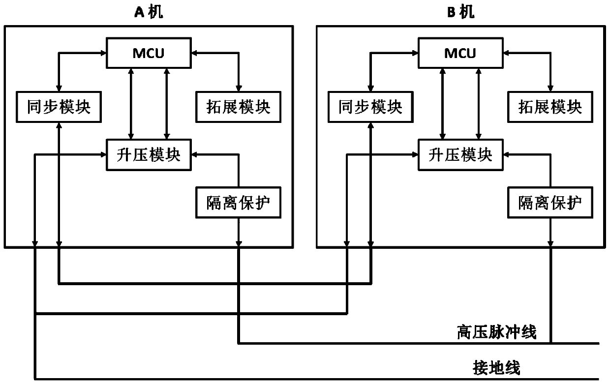
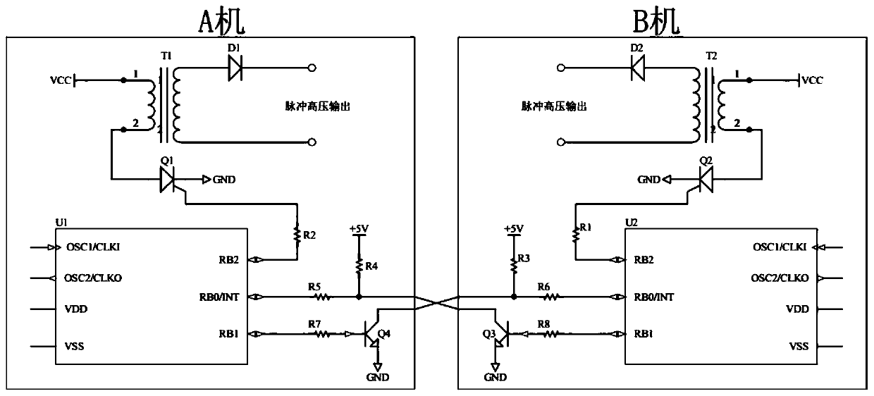
[0020] refer to Figure 1 to Figure 2 , the present invention provides an energy control system for energy multiplication, including several energy controllers, each of which includes an MCU and a boost module, a synchronization module, and an isolation protection module connected to the periphery of the MCU. The isolation protection module in the controller is also electrically connected to the booster module, the isolation protection module in each energy controller is electrically connected through a high-voltage pulse line, and the synchronization modules in every two adjacent energy controllers are electrically connected, The boost module in each energy controller is grounded.

[0021] The energy controller also includes an expansion module, which is selected from any one or more of a voltage detection module, a status display module, and...


PUM


Abstract

The invention discloses an energy-multiplying energy control system, which comprises a plurality of energy controllers. Each energy controller comprises an MCU, a boosting module, a synchronization module and an isolation protective module, wherein the boosting module, the synchronization module and the isolation protective module are all connected to the outer periphery of the MCU. In the same energy controller, the isolation protective module is further electrically connected with the boosting module. The isolation protective modules in all energy controllers are electrically connected through a high-voltage pulse wire; the synchronization modules in every two adjacent energy controllers are electrically connected; the boosting module in each energy controller is grounded. The energy controllers can be flexibly increased or reduced according to requirements of onsite environments, availability for hot plug is realized, and energy of an external net boundary changes as well; when onedevice is damaged, operation of another device is unaffected, a whole boundary still has a striking effect, and accordingly boundary reliability is improved, safety experience of users is improved, and integral use cost is reduced.

Description

technical field [0001] The present invention relates to energy control technology, in particular to an energy multiplication energy control system, which is suitable for security perimeter sites, and is applicable to all occasions where tangible wires are used to transmit high-voltage shock pulses, such as electronic fences and pasture energy controllers. Background technique [0002] Electronic fences first originated in European pastures. For the needs of grazing, shepherds pulled a wire and connected pulse electricity to form a simple electronic fence to make livestock move within a certain range. When cattle and sheep touch the high-voltage pulse line of the electronic fence, they will be shocked back by electric shock, which plays the role of "shepherd" well, and at the same time prevents large animals or beasts outside the fence from running in, which is very important for the development of animal husbandry. to a greater promotion. The electronic fence industry at th...

Claims


Application Information

Patent Timeline
Patent Type & Authority Applications(China)
IPC IPC(8): G08B13/12G08B15/00A01K3/00H05C1/06
Inventor 胡相才
Owner SHENZHEN LANSTAR TECH
Learn More