
Angle-adjustable inclined plane anchor rod tray

A pallet and slope technology, which is applied in the installation of bolts, mining equipment, earthwork drilling and mining, etc., can solve the problems of deformation and fracture of the connecting surface, weak bearing capacity, poor adaptability, etc., and achieve a wide range of slope angles, strong bearing capacity, and structural stable effect

Pending Publication Date: 2019-05-24
WUHAN UNIV OF SCI & TECH
View PDF1 Cites 0 Cited by
  • Summary
  • Abstract
  • Description
  • Claims
  • Application Information

AI Technical Summary

Problems solved by technology

However, the angle of the pallet must be produced according to the angle of the anchor rod, and it cannot be adjusted by itself during use, and the adaptability is poor.
In addition, the pallet is concentrated on the connecting surface, which is easy to cause deformation and breakage at the connecting surface, and the bearing capacity is weak

Method used


Image

  • Angle-adjustable inclined plane anchor rod tray
  • Angle-adjustable inclined plane anchor rod tray
  • Angle-adjustable inclined plane anchor rod tray

Examples


Embodiment 1

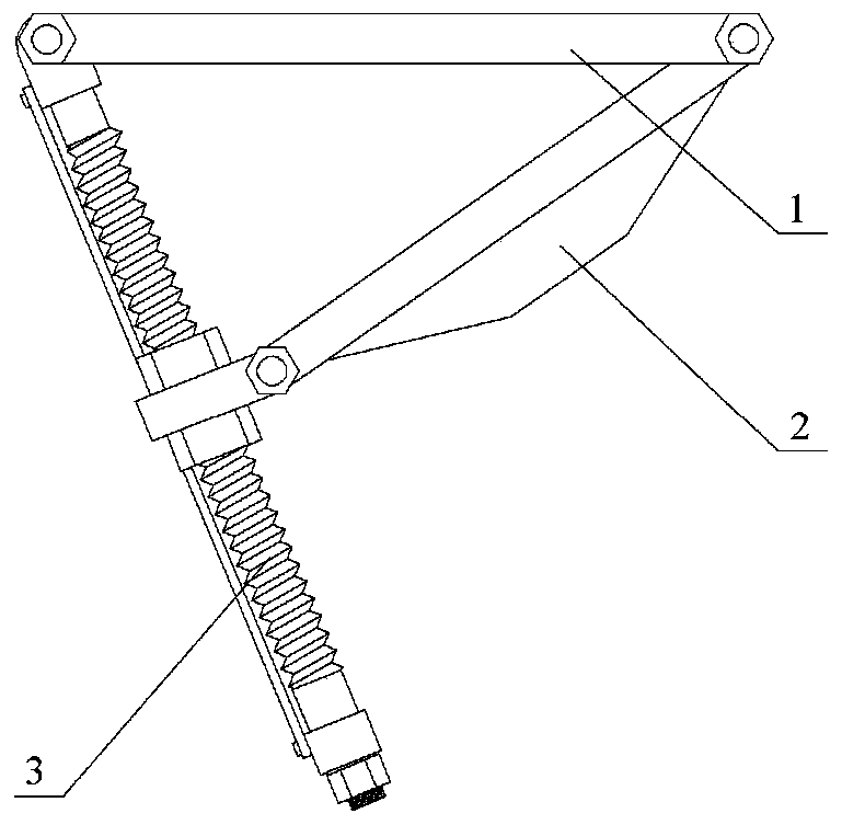
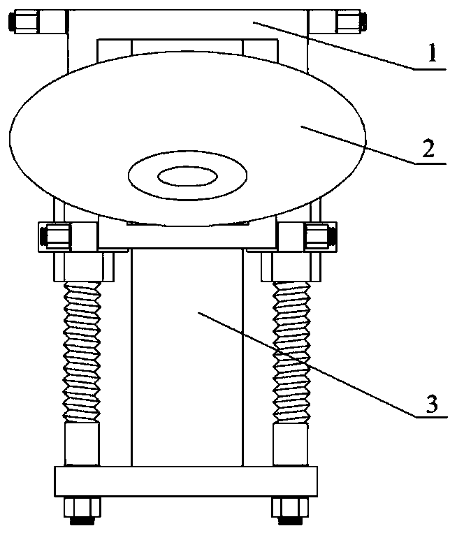
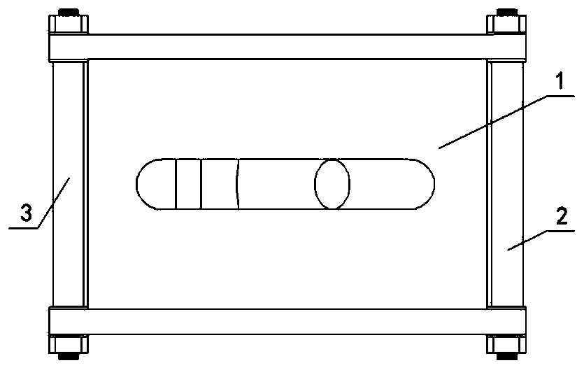
[0034] An angle-adjustable sloped anchor tray. Such as figure 1 , figure 2 , image 3 As shown, the inclined anchor pallet is composed of a pallet top plate 1, a pallet frame 2 and a support frame 3. The upper end of the tray frame 2 is connected by bolts with one end of the tray top plate 1, the other end of the tray top plate 1 is connected with the upper end of the support frame 3 by bolts, and the middle part of the support frame 3 is connected with the lower end of the tray frame 2 by bolts.

[0035] Such as Figure 4 and Figure 5 As shown, the pallet top plate 1 is composed of a rectangular plate 4 and two reinforcing rods 5 . A strip-shaped hole 6 is opened at the centroid of the rectangular plate 4 , and the long sides of the strip-shaped hole 6 are parallel to the long sides of the rectangular plate 4 . The two long sides of the rectangular plate 4 are symmetrically fixed with reinforcing rods 5, the two ends of the reinforcing rods 5 protrude from the rectang...

Embodiment 2

[0045] An angle-adjustable sloped anchor tray. Except following technical parameter, all the other are with embodiment 1:

[0046] The lengths of the two protruding ends of the reinforcing rod 5 are both 18-20mm;

[0047] The diameter of the large surface of the circular table 9 is 0.8 to 0.85 times of the axial length of the frame 8 .

[0048] Compared with the prior art, this specific embodiment has the following positive effects:

[0049] When this specific embodiment is in use, the rectangular plate 4 of the tray top plate 1 is first pressed against the rock wall 18, and the position of the hinged collar 13 on the threaded rod 14 is adjusted so that the centerline of the anchor hole 10 of the tray frame 2 is in line with the rock wall 18. The center line of the drilling hole on the wall 18 coincides, then adjust the collar fixing nut 12, clamp the hinged collar 13, and then connect the tray top plate 1 and the tray frame 2, the tray top plate 1 and the support frame 3, a...


PUM

PropertyMeasurementUnit
Thicknessaaaaaaaaaa
Thicknessaaaaaaaaaa
Thicknessaaaaaaaaaa

Abstract

The invention relates to an angle-adjustable inclined plane anchor rod tray. According to the technical scheme, the inclined plane anchor rod tray consists of a tray top plate (1), a tray frame (2) and a support frame (3). The upper end of the tray frame (2) is connected with one end of the tray top plate (1) through bolts, the other end of the tray top plate (1) is connected with the upper end ofthe support frame (3) through bolts, and the middle of the support frame (3) is connected with the lower end of the tray frame (2) through bolts. The tray top plate (1) consists of a rectangular plate (4) and two reinforcing rods (5) which are parallel along the long sides; the tray frame (2) consists of a frame (8) and a round table (9); and according to the support frame (3), two threaded rods(14) arranged in parallel penetrate through a connecting rod (11), a hinged lantern ring (13) and lantern ring fixing nuts (12) on two sides of the hinged lantern ring and are spirally fixed to counter bores on fixing rods (16), and strip-shaped plates (15) are arranged in the middles of the connecting rod (11) and the fixing rods (16). The angle-adjustable inclined plane anchor rod tray is stablein structure, strong in bearing capacity and wide in inclined plane angle range.

Description

technical field [0001] The invention belongs to the technical field of pallets. In particular, it relates to an angle-adjustable inclined-plane anchor tray. Background technique [0002] Bolt support is to use metal rods, polymer materials and other materials to drive into the rock mass to produce a reinforcement effect. By installing a tray and nut at the end of the bolt exposed to the rock wall, and applying a certain pre-tightening force to improve the anchor Rod support effect. [0003] Under normal circumstances, when anchoring into the bolt, the bolt is required to be vertical to the rock wall. However, under special conditions, such as the section of the roadway is too small or affected by the dip angle of the rock formation, bedding plane, and crack surface, the drilling direction cannot be perpendicular to the rock wall in order to facilitate construction and ensure the support effect. In this case, the contact between the pallet and the rock wall becomes a line ...

Claims


Application Information

Patent Timeline
IPC IPC(8): E21D21/00
Inventor 叶义成陈虎王其虎姚囝罗斌玉李鹏程刘冉江慧敏
Owner WUHAN UNIV OF SCI & TECH
Learn More