Double-clip type pot seedling transplanting and clamping device with double clamps
A double-clamp type, clamping hand technology, applied in the field of agricultural machinery, can solve the problems of easy damage to seedlings, decreased productivity, and rising wages.
- Summary
- Abstract
- Description
- Claims
- Application Information
AI Technical Summary
Problems solved by technology
Method used
Image
Examples
Embodiment 1
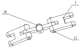
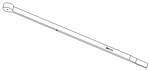
[0013] Embodiment 1: refer to figure 1 , 2 , 3, and 4, the present invention discloses a double-clip type pot seedling transplanting and clamping device with double clamping hands, including a power unit, a connecting device, a frame (5), a clamping hand, and a clamping piece (6 ), which is characterized in that the motor (1) provides power for the device, the motor (1) is fixed on the top of the frame (5) and connected by a connecting device, and the clips (6) are fixed on both symmetrical sides of the frame (5). The hand is fixed on the inside of the clip (6) and is connected with the lower center drive rod (15) with a spring (16).
Embodiment 2
[0014] Embodiment 2: The difference between this embodiment and Embodiment 1 is that the power device includes a motor (1), a threaded rod (2), a lead screw nut seat (10), and the motor (1) is located on the threaded rod (2). Above, the lead screw nut seat (10) is located below the threaded rod (2), the power provided by the motor (1) drives the threaded rod (2), and the threaded rod (2) drives the lead screw nut seat (10) through transmission.
Embodiment 3
[0015] Embodiment 3: The difference between this embodiment and Embodiment 1 is that the connecting device includes a screw nut seat (10), an L-shaped connector (3), an upper center drive rod (4), a frame (5), Clip (6), baffle (12), lower plate (14), H-shaped connector (7), lower center drive rod (15), large bolt (13), small bolt (11), spring (16) , Gripper, the lead screw nut seat (10) is fixed on one side of the L-shaped connector (3) by a small bolt (11), and the other side of the L-shaped connector (3) is connected to the upper center drive rod (4) , the upper center driving rod (4) can move up and down in the center of the rack (5) when it is placed in the center of the rack (5), and the upper center of the rack (5) is fixedly connected with the baffle (12) to reduce The wear of the rod (4) and the frame (5), the clip (6) is located on both sides of the frame (5) and connected with large bolts (13), the upper center drive rod (4) and the lower center drive rod (15) The l...
PUM
 Abstract
Description
Claims
Application Information
 - Generate Ideas
- Intellectual Property
- Life Sciences
- Materials
- Tech Scout
- Unparalleled Data Quality
- Higher Quality Content
- 60% Fewer Hallucinations
Browse by: Latest US Patents, China's latest patents, Technical Efficacy Thesaurus, Application Domain, Technology Topic, Popular Technical Reports.
© 2025 PatSnap. All rights reserved.Legal|Privacy policy|Modern Slavery Act Transparency Statement|Sitemap|About US| Contact US: help@patsnap.com


