Voltage-controlled oscillator and phase-locked loop

A voltage-controlled oscillator and filter technology, applied in the field of oscillators, phase-locked loops, and voltage-controlled oscillators, can solve the problems of increased circuit area and cost, low tolerance of voltage-controlled oscillators, and reduction of voltage-controlled oscillators

Pending Publication Date: 2019-05-21
REALTEK SEMICON CORP
View PDF5 Cites 0 Cited by
  • Summary
  • Abstract
  • Description
  • Claims
  • Application Information

AI Technical Summary

Problems solved by technology

[0003] However, the oscillation frequency of the voltage-controlled oscillator will be affected by the process, temperature, and voltage, and the low-gain voltage-controlled oscillator is less tolerant to the above-mentioned effects
In order to prevent the output frequency of the voltage-controlled oscillator from being seriously affected, it is known that the low-gain voltage-controlled oscillator will be equipped with an additional frequency correction circuit to eliminate the variation of the process, but the frequency offset caused by the change of temperature and voltage is still It may make the output frequency of the voltage controlled oscillator exceed the expected range. Since most systems using the phase locked loop do not allow the phase locked loop to set aside time to re-calibrate the frequency during normal operation, the gain of the voltage controlled oscillator cannot be constant. ambiguity is reduced to reduce jitter, at least large enough to cover temperature and voltage variations
[0004] Based on the above, although high-gain VCOs are more tolerant to the influence of process, temperature, and voltage, however, as product specifications set stricter jitter requirements, high-gain VCOs must use huge loops filter to meet the jitter requirement, the loop filter must even be implemented by an external capacitor on the chip, which leads to an increase in circuit area and cost

Method used


Image

  • Voltage-controlled oscillator and phase-locked loop
  • Voltage-controlled oscillator and phase-locked loop
  • Voltage-controlled oscillator and phase-locked loop

Examples


Embodiment Construction

[0016] The terms used in the following explanations refer to the customary terms in this technical field. If some terms are explained or defined in this manual, the explanations of these terms shall be based on the descriptions or definitions in this manual.

[0017] The invention discloses a voltage-controlled oscillator and a phase-locked loop containing the voltage-controlled oscillator or its equivalent, which can provide equivalently the gain of the high-voltage controlled oscillator for the slow change of the input voltage to increase the influence on the process, temperature, voltage, etc. tolerance and effectively provides LCO gain for fast changes in input voltage to reduce jitter.

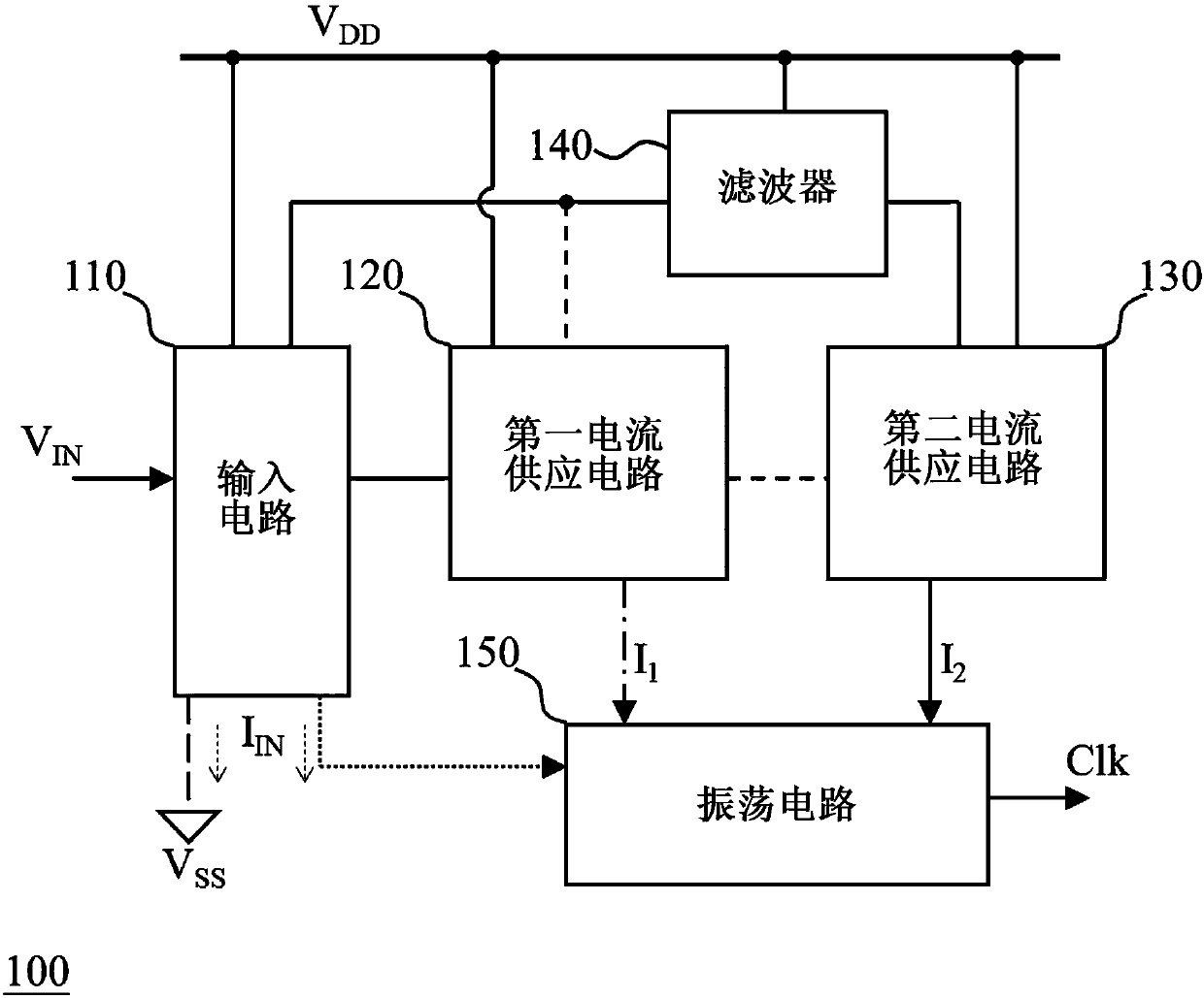
[0018] figure 1 One embodiment of the voltage-controlled oscillator of the present invention is shown. figure 1 The voltage controlled oscillator 100 includes an input circuit 110 , a first current supply circuit 120 , a second current supply circuit 130 , a filter 140 , and an oscillati...


PUM


Abstract

The invention discloses a voltage-controlled oscillator and a phase-locked loop, which can equivalently provide a high-voltage-controlled oscillator gain for the slow change of an input voltage so asto increase the tolerance to processes, temperatures, voltages and the like, and equivalently provide a low-voltage-controlled oscillator gain for the fast change of the input voltage so as to reducejitter. One embodiment of the voltage-controlled oscillator comprises an input circuit used for generating an input current according to an input voltage; a first current supply circuit used for generating a first output current according to the input current; a second current supply circuit used for generating a second output current according to the input current; a filter coupled with the inputcircuit and the second current supply circuit, and used for reducing the influence speed of the change of the input current on the second current supply circuit; and an oscillating circuit used for generating an output frequency according to the first output current and the second output current.

Description

technical field [0001] The present invention relates to an oscillator and a phase-locked loop, and in particular to a voltage-controlled oscillator and a phase-locked loop using the voltage-controlled oscillator or its equivalent. Background technique [0002] The jitter (ie phase noise) of the output signal of a PLL reflects the output performance of the PLL. Based on the same input noise, the output jitter of the phase-locked loop of the VCO with smaller gain is smaller. Therefore, in order to realize a low-jitter PLL, a low-gain VCO is necessary. [0003] However, the oscillating frequency of the VCO is affected by process, temperature, and voltage, and the low-gain VCO has low tolerance to the above effects. In order to prevent the output frequency of the voltage-controlled oscillator from being seriously affected, it is known that the low-gain voltage-controlled oscillator will be equipped with an additional frequency correction circuit to eliminate the variation of t...

Claims


Application Information

Patent Timeline
IPC IPC(8): H03L7/099
CPCY02D30/70
Inventor 蔡松林吴国维林见儒
Owner REALTEK SEMICON CORP
Why Eureka
Try Eureka